Computer Architecture Organization(CAO)

Introduction to Computer Organization:

  • Introduction to Computer.
  • Introduction to CPU(Central Processing Unit).
  • (Computer Organization,
  • Computer Design,
  • Computer Architecture).
  • Stored Program Concepts.
  • Von Neumann Architecture
  • Register Transfer Language(RTL)
  • Bus And Memory Transfer.
  • Micro-operations And Types Of Micro-operation.
  • Arithmetic micro-operations
  • Logic micro-operations
  • Shift micro-operations

Computer Organization and Architecture 

Computer Organization and Architecture is used to design computer systems. Computer Architecture is considered to be those attributes of a system that are visible to the user like addressing techniques, instruction sets, and bits used for data, and have a direct impact on the logic execution of a program, It defines the system in an abstract manner, It deals with What does the system do.

Whereas, Computer Organization is the way in which a system has to structure and It is operational units and the interconnections between them that achieve the architectural specifications, It is the realization of the abstract model, and It deals with How to implement the system.

Introduction to Computer.

computer is an electronic device that accepts data from the user, processes it, produces results, displays them to the users, and stores the results for future usage.

Data is a collection of unorganized facts & figures and does not provide any further information regarding patterns, context, etc. Hence data means “unstructured facts and figures”.

Information is a structured data i.e. organized meaningful and processed data. To process the data and convert into information, a computer is used.

Types of computer:

the computer is of three types:

  • Analogue Computer
  • Digital Computer
  • Hybrid Computer

1) Analogue Computer

Analogue computers are designed to process analogue data. Analogue data is continuous data that changes continuously and cannot have discrete values. We can say that analogue computers are used where we don’t need exact values always such as speed, temperature, pressure and current.

Analogue computers directly accept the data from the measuring device without first converting it into numbers and codes. They measure the continuous changes in physical quantity and generally render output as a reading on a dial or scale. Speedometer and mercury thermometer are examples of analogue computers.

Advantages of using analogue computers:

  • It allows real-time operations and computation at the same time and continuous representation of all data within the rage of the analogue machine.
  • In some applications, it allows performing calculations without taking the help of transducers for converting the inputs or outputs to digital electronic form and vice versa.
  • The programmer can scale the problem for the dynamic range of the analogue computer. It provides insight into the problem and helps understand the errors and their effects.

Types of analogue computers:

  • Slide Rules: It is one of the simplest types of mechanical analogue computers. It was developed to perform basic mathematical calculations. It is made of two rods. To perform the calculation, the hashed rod is slid to line up with the markings on another rod.
  • Differential Analysers: It was developed to perform differential calculations. It performs integration using wheel-and-disc mechanisms to solve differential calculations.
  • Castle Clock: It was invented by Al-Jarazi. It was able to save programming instructions. Its height was around 11 feet and it was provided with the display of time, the zodiac, and the solar and lunar orbits. This device also could allow users to set the length of the day as per the current season.
  • Electronic Analogue Computer: In this type of analogue computer, electrical signals flow through capacitors and resistors to simulate physical phenomena. Here, the mechanical interaction of components does not take place. The voltage of the electrical signal generates the appropriate displays.

2) Digital Computer

Digital computer is designed to perform calculations and logical operations at high speed. It accepts the raw data as input in the form of digits or binary numbers (0 and 1) and processes it with programs stored in its memory to produce the output. All modern computers like laptops, desktops including smartphones that we use at home or office are digital computers.

Advantages of digital computers:

  • It allows you to store a large amount of information and to retrieve it easily whenever you need it.
  • You can easily add new features to digital systems more easily.
  • Different applications can be used in digital systems just by changing the program without making any changes in hardware
  • The cost of hardware is less due to the advancement in the IC technology.
  • It offers high speed as the data is processed digitally.
  • It is highly reliable as it uses error correction codes.
  • Reproducibility of results is higher as the output is not affected by noise, temperature, humidity, and other properties of its components.

3) Hybrid Computer

Hybrid computer has features of both analogue and digital computer. It is fast like an analogue computer and has memory and accuracy like digital computers. It can process both continuous and discrete data. It accepts analogue signals and convert them into digital form before processing. So, it is widely used in specialized applications where both analogue and digital data is processed. For example, a processor is used in petrol pumps that converts the measurements of fuel flow into quantity and price. Similarly, they are used in airplanes, hospitals, and scientific applications.

Advantages of using hybrid computers:

  • Its computing speed is very high due to the all-parallel configuration of the analogue subsystem.
  • It produces precise and quick results that are more accurate and useful.
  • It has the ability to solve and manage big equation in real-time.
  • It helps in the on-line data processing.

On the basis of size, the computer can be of five types:

1) Supercomputer

Supercomputers are the biggest and fastest computers. They are designed to process huge amount of data. A supercomputer can process trillions of instructions in a second. It has thousands of interconnected processors.

Supercomputers are particularly used in scientific and engineering applications such as weather forecasting, scientific simulations and nuclear energy research. The first supercomputer was developed by Roger Cray in 1976.

Characteristics or applications of supercomputers:

  • It has the ability to decrypt your password to enhance protection for security reasons.
  • It produces excellent results in animations.
  • It is used for virtual testing of nuclear weapons and critical medical tests.
  • It can study and understand climate patterns and forecast weather conditions. It can run in NOAA’s system (National Oceanic and Atmospheric Administration) that can execute any type of simple and logical data.
  • It helps in designing the flight simulators for pilots at the beginner level for their training.
  • It helps in extracting useful information from data storage centres or cloud system. For example, in insurance companies.
  • It has played a vital role in managing the online currency world such as stock market and bitcoin.
  • It helps in the diagnosis of various critical diseases and in producing accurate results in brain injuries, strokes, etc.
  • It helps in scientific research areas by accurately analysing data obtained from exploring the solar system, satellites, and movement of Earth.
  • It also used in a smog control system where it predicts the level of fog and other pollutants in the atmosphere.

2) Mainframe computer

Mainframe computers are designed to support hundreds or thousands of users simultaneously. They can support multiple programs at the same time. It means they can execute different processes simultaneously. These features of mainframe computers make them ideal for big organizations like banking and telecom sectors, which need to manage and process high volume of data.

Mainframe computers are designed to support hundreds or thousands of users simultaneously. They can support multiple programs at the same time. It means they can execute different processes simultaneously. These features of mainframe computers make them ideal for big organizations like banking and telecom sectors, which need to manage and process a high volume of data that requires integer operations such as indexing, comparisons, etc.

Characteristics of Mainframe Computers:

  • It can process huge amount of data, e.g. millions of transactions in a second in the banking sector.
  • It has a very long life. It can run smoothly for up to 50 years after proper installation.
  • It gives excellent performance with large scale memory management.
  • It has the ability to share or distribute its workload among other processors and input/output terminals.
  • There are fewer chances of error or bugs during processing in mainframe computers. If any error occurs it can fix it quickly without affecting the performance.
  • It has the ability to protect the stored data and other ongoing exchange of information and data.

Applications of mainframe computers:

  • In health care, it enabled hospitals to maintain a record of their millions of patients in order to contact them for treatment or related to their appointment, medicine updates or disease updates.
  • In the field of defence, it allows the defence departments to share a large amount of sensitive information with other branches of defence.
  • In the field of education, it helps big universities to store, manage and retrieve data related to their courses, admissions, students, teachers, employees and affiliated schools and colleges.
  • In the retail sector, the retail companies that have a huge customer base and branches use mainframe computers to handle and execute information related to their inventory management, customer management, and huge transactions in a short duration.

3) Miniframe or Minicomputer

It is a midsize multiprocessing computer. It consists of two or more processors and can support 4 to 200 users at one time. Miniframe computers are used in institutes and departments for tasks such as billing, accounting and inventory management. A minicomputer lies between the mainframe and microcomputer as it is smaller than mainframe but larger than a microcomputer.

Characteristics of miniframe or minicomputer:

  • It is light weight that makes it easy to carry and fit anywhere.
  • It is less expensive than mainframe computers.
  • It is very fast compared to its size.
  • It remains charged for a long time.
  • It does not require a controlled operational environment.

Applications of minicomputers:

A minicomputer is mainly used to perform three primary functions, which are as follows:

  • Process control: It was used for process control in manufacturing. It mainly performs two primary functions that are collecting data and feedback. If any abnormality occurs in the process, it is detected by the minicomputer and necessary adjustments are made accordingly.
  • Data management: It is an excellent device for small organizations to collect, store and share data. Local hospitals and hotels can use it to maintain the records of their patients and customers respectively.
  • Communications Portal: It can also play the role of a communication device in larger systems by serving as a portal between a human operator and a central processor or computer.

4) Workstation

Workstation is a single user computer that is designed for technical or scientific applications. It has a faster microprocessor, a large amount of RAM and high speed graphic adapters. It generally performs a specific job with great expertise; accordingly, they are of different types such as graphics workstation, music workstation and engineering design workstation.

Characteristics of workstation computer:

  • It is a high-performance computer system designed for a single user for business or professional use.
  • It has larger storage capacity, better graphics, and more powerful CPU than a personal computer.
  • It can handle animation, data analysis, CAD, audio and video creation and editing.

Any computer that has the following five features, can be termed as a workstation or can be used as a workstation.

  • Multiple Processor Cores: It has more processor cores than simple laptops or computers.
  • ECC RAM: It is provided with Error-correcting code memory that can fix memory errors before they affect the system’s performance.
  • RAID (Redundant Array of Independent Disks): It refers to multiple internal hard drives to store or process data. RAID can be of different types, for example, there can be multiple drives to process data or mirrored drives where if one drive does not work than other starts functioning.
  • SSD: It is better than conventional hard-disk drives. It does not have moving parts, so the chances of physical failure are very less.
  • Optimized, Higher end GPU: It reduces the load on CPU. E.g., CPU has to do less work while processing the screen output.

5) Microcomputer

Microcomputer is also known as a personal computer. It is a general-purpose computer that is designed for individual use. It has a microprocessor as a central processing unit, memory, storage area, input unit and output unit. Laptops and desktop computers are examples of microcomputers. They are suitable for personal work that may be making an assignment, watching a movie, or at office for office work.

Characteristics of a microcomputer:

  • It is the smallest in size among all types of computers.
  • A limited number of software can be used.
  • It is designed for personal work and applications. Only one user can work at a time.
  • It is less expansive and easy to use.
  • It does not require the user to have special skills or training to use it.
  • Generally, comes with single semiconductor chip.
  • It is capable of multitasking such as printing, scanning, browsing, watching videos, etc.

Block Diagram OF computer system

CPU(Central Processing Unit)

The full form of CPU is Central Processing Unit . It is a brain of the computer. All types of data processing operations and all the important functions of a computer are performed by the CPU. It helps input and output devices to communicate with each other and perform their respective operations. It also stores data which is input, intermediate results in between processing, and instructions. 

What is a CPU?

A Central Processing Unit is the most important component of a computer system. A CPU is a hardware that performs data input/output, processing and storage functions for a computer system. A CPU can be installed into a CPU socket. These sockets are generally located on the motherboard. CPU can perform various data processing operations. CPU can store data, instructions, programs, and intermediate results.

Different Parts of CPU

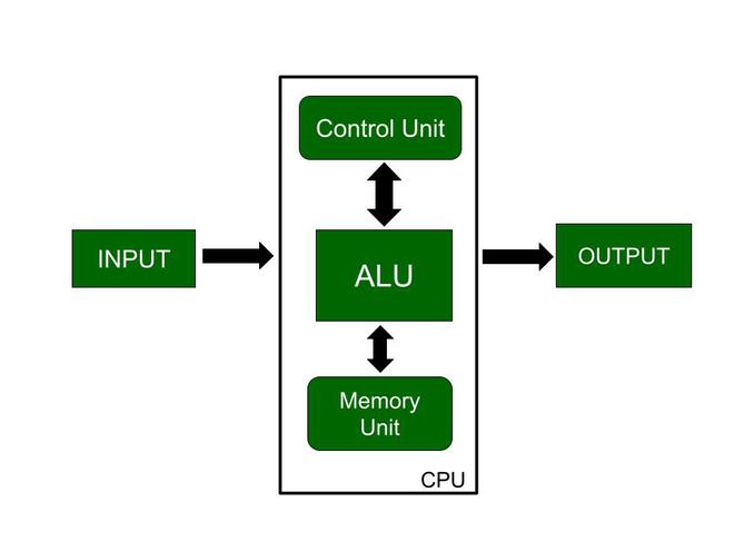
Now, the CPU consists of 3 major units, which are:

  1. Memory or Storage Unit
  2. Control Unit
  3. ALU(Arithmetic Logic Unit)

CPU

Here, in this diagram, the three major components are also shown. So, let us discuss these major components:

Memory or Storage Unit

As the name suggests this unit can store instructions, data, and intermediate results. The memory unit is responsible for transferring information to other units of the computer when needed. It is also known as an internal storage unit or the main memory or the primary storage or Random Access Memory (RAM) as all these are storage devices.

Its size affects speed, power, and performance. There are two types of memory in the computer, which are primary memory and secondary memory. Some main functions of memory units are listed below:

  • Data and instructions are stored in memory units which are required for processing.
  • It also stores the intermediate results of any calculation or task when they are in process.
  • The final results of processing are stored in the memory units before these results are released to an output device for giving the output to the user.
  • All sorts of inputs and outputs are transmitted through the memory unit.

Control Unit

As the name suggests, a control unit controls the operations of all parts of the computer but it does not carry out any data processing operations. For executing already stored instructions, It instructs the computer by using the electrical signals to instruct the computer system. It takes instructions from the memory unit and then decodes the instructions after that it executes those instructions. So, it controls the functioning of the computer. It’s main task is to maintain the flow of information across the processor. Some main functions of the control unit are listed below:

  • Controlling of data and transfer of data and instructions is done by the control unit among other parts of the computer.
  • The control unit is responsible for managing all the units of the computer.
  • The main task of the control unit is to obtain the instructions or data which is input from the memory unit, interprets them, and then directs the operation of the computer according to that.
  • The control unit is responsible for communication with Input and output devices for the transfer of data or results from memory.
  • The control unit is not responsible for the processing of data or storing data.

ALU (Arithmetic Logic Unit) 

ALU (Arithmetic Logic Unit) is responsible for performing arithmetic and logical functions or operations. It consists of two subsections, which are:

  • Arithmetic Section
  • Logic Section

Arithmetic Section: By arithmetic operations, we mean operations like addition, subtraction, multiplication, and division, and all these operation and functions are performed by ALU. Also, all the complex operations are done by making repetitive use of the mentioned operations by ALU.

Logic Section: By Logical operations, we mean operations or functions like selecting, comparing, matching, and merging the data, and all these are performed by ALU.

Types of Computer Memory

  • Cache memory. This temporary storage area, known as a cache, is more readily available to the processor than the computer’s main memory source. It is also called CPU memory because it is typically integrated directly into the CPU chip or placed on a separate chip with a bus interconnect with the CPU.
  • RAM.  It is one of the parts of the Main memory, also famously known as Read Write Memory. Random Access memory is present on the motherboard and the computer’s data is temporarily stored in RAM. As the name says, RAM can help in both Read and write.
  • D RAM (Dynamic RAM): D RAM uses capacitors and transistors and stores the data as a charge on the capacitors. They contain thousands of memory cells. It needs refreshing of charge on capacitor after a few milliseconds. This memory is slower than S RAM.
  • S RAM (Static RAM): S RAM uses transistors and the circuits of this memory are capable of retaining their state as long as the power is applied. This memory consists of the number of flip flops with each flip flop storing 1 bit. It has less access time and hence, it is faster.
  • ROM: ROM full form is Read Only Memory. ROM is a non volatile memory and it is used to store important information which is used to operate the system. We can only read the programs and data stored on it and can not modify of delete it.
  • MROM(Masked ROM): Hard-wired devices with a pre-programmed collection of data or instructions were the first ROMs. Masked ROMs are a type of low-cost ROM that works in this way.
  • PROM (Programmable Read Only Memory): This read-only memory is modifiable once by the user. The user purchases a blank PROM and uses a PROM program to put the required contents into the PROM. Its content can’t be erased once written.
  • EPROM (Erasable Programmable Read Only Memory): EPROM is an extension to PROM where you can erase the content of ROM by exposing it to Ultraviolet rays for nearly 40 minutes.
  • EEPROM (Electrically Erasable Programmable Read Only Memory): Here the written contents can be erased electrically. You can delete and reprogramme EEPROM up to 10,000 times. Erasing and programming take very little time, i.e., nearly  4 -10 ms(milliseconds). Any area in an EEPROM can be wiped and programmed selectively.
  • Virtual memory. A memory management technique where secondary memory can be used as if it were a part of the main memory. Virtual memory uses hardware and software to enable a computer to compensate for physical memory shortages by temporarily transferring data from RAM to disk storage.


Units of Memory

Memory units are used to measure the size and represent data. Some of the commonly used memory units are:

1. Bit

The first memory location in a computer is bit. The smallest measurement unit for data held in primary memory and storage devices is a bit. Out of the binary values 0 and 1, a bit can only have one.

  • The smallest measurement unit for data in primary memory and storage devices.
  • Represents binary values 0 and 1.

2. Nibble

  • It means the group of 4 bits. 

3. Word

It is a fixed number of bits, it is different from computer to computer, but the same for each device. Compute store information in the form of words. 

  • A fixed number of bits that varies across computers but remains consistent within each device.
  • Used to store information in computers.

4. Bytes

The fundamental unit used to measure data is the byte. It has 8 bits in it. A byte can therefore represent 2 * 8 or 256 values. They determine the size of files, documents, photos, and other kinds of data.

  • The fundamental unit for measuring data, consisting of 8 bits.
  • Represents 256 values and determines file, document, photo, and data sizes.

5. Kilobyte

1024 bytes is equal to one kilobyte. It is widely used to denote small file sizes and data storage capacities. One kilobyte can hold a small image or around 1024 characters of text. It frequently shows up in text documents, spreadsheets, and small image files.

  • Equal to 1024 bytes.
  • Denotes small file sizes and storage capacities.
  • Can hold small images or around 1024 characters of text.

6. Meghabyte

A megabyte is 1024 kilobytes in size. It contains more info as compared to a kilobyte. A megabyte can hold longer texts, high-resolution images, and short audio clips. It is used to calculate the size of files comprising music and short films, software packages, and documents. Megabytes are still important and frequently used, even though larger units of measurement are being used more frequently as a result of the growing number of data files.

  • Comprising 1024 kilobytes.
  • Contains more information compared to a kilobyte.
  • Holds longer texts, high-resolution images, and short audio clips.
  • Measures file sizes of music, short films, software packages, and documents.

7. Gigabyte

1024 megabytes is equal to one gigabyte. It has a substantial amount of data storage space. Larger files, such full photo albums, high-definition movies, and software programs can fit within a gigabit. The storage capabilities of hard drives, solid-state drives, and other forms of data storage devices are routinely assessed utilizing this technique.

  • Equal to 1024 megabytes.
  • Offers substantial data storage space.
  • Suitable for larger files, such as full photo albums, high-definition movies, and software programs.

8. Terabyte

A terabyte is made up of 1024 gigabytes. It has a substantial amount of data storing capacity. A terabyte can hold a lot of data in large databases, massive media collections, and enterprise-level storage systems. It is frequently used by data centers, cloud storage services, and external hard drives with large storage capacities. As the demand for large-scale data processing and storage grows, terabytes are becoming more and more important.

  • Comprising 1024 gigabytes.
  • Provides substantial data storing capacity.
  • Holds large databases, media collections, and enterprise-level storage systems.

9. Petabyte

A petabyte is a colossal unit of data storage capacity. A petabyte may hold massive amounts of data, including significant video libraries, sizable databases, and sizable collections of high-resolution pictures. It is often used in data centers, cloud storage, and scientific research that uses a lot of data.

  • A colossal unit of data storage capacity.
  • Stores massive data quantities, like video libraries and large databases.

10. Exabyte (1024 petabytes)

An exabyte is equal to one EB. It has a substantial amount of data storage space. Exabytes can store vast film archives, massive data warehouses, and global internet traffic. It is extensively used in large-scale scientific simulations, cloud computing infrastructures, and enterprise-level storage systems.

  • Equal to 1024 petabytes.
  • Holds vast film archives, data warehouses, and global internet traffic.

11. Zettabyte (1024 exabytes)

A zettabyte. It represents a capacity for data storage that is almost unimaginable. Zettabytes have the capacity to store unfathomably large amounts of data, including worldwide internet content, long-term archival storage, and in-depth global data analysis.

  • Represents an almost unimaginable data storage capacity.
  • Stores worldwide internet content, long-term archival data, and extensive global analysis.

12. Yottabyte

1024 zettabytes make up a yottabyte (abbreviated YB). It stands for an incredible amount of data storage. Unimaginable amounts of data, such as the equivalent of storing all of the material on the internet numerous times or tracking vast amounts, may be stored in yottabytes.

  • Comprising 1024 zettabytes.
  • Stands for an incredible amount of data storage.
  • Can hold vast amounts equivalent to storing internet content numerous times.

Conversations of units

Name Equal To Size (In Bytes)
Bit 1 Bit 1/8
Nibble 4 Bits 1/2 (rare)
Byte 8 Bits 1
Kilobyte 1024 Bytes 1024
Megabyte 1024 Kilobytes 1, 048, 576
Gigabyte 1024 Megabytes 1, 073, 741, 824
Terabyte 1024 Gigabytes 1, 099, 511, 627, 776
Petabyte 1024 Terabytes 1, 125, 899, 906, 842, 624
Exabyte 1024 Petabytes 1, 152, 921, 504, 606, 846, 976
Zettabyte 1024 Exabytes 1, 180, 591, 620, 717, 411, 303, 424
Yottabyte 1024 Zettabytes 1, 208, 925, 819, 614, 629, 174, 706, 176

Secondary storage unit

Secondary storage, sometimes termed auxiliary storage, refers to the storage of data that is not accessed frequently as the data in primary storage. It is a non-volatile memory medium that preserves data until and unless it has been deleted or overwritten. Secondary storage can be hosted on-premises, on an external device or in the cloud. With a variety of media types available, secondary storage enables organizations to store data ranging from a few megabytes to petabytes.

Input unit

The Input Unit means the data we write on a computer which data the computer receives and the Output Unit means that the data which is sent by the computer. The processing unit is the device that handles all the instructions which are given by the human for the input unit or the output unit.

The Input Unit: Computer Input unit means the device of the input and a part of the computer hardware which is used for the transport of the data processing system involves the information devices of the computer with the control and data signals of the computer.

Example – Mouse, Camera, and Keyboard

The Output Unit: Computer Output is the device which deals with transmitting the data of the computer among the device and the clients. The computer is designed for humans in the form of audio and video format.

Example – Monitors, printers, microphones, and headphones.

The Processing Unit: The Processing Unit is the hardware device of the computer that deals with the instruction of the computer program and is known as the CPU (central processing unit). It deals with the basic logical information of the computer and arithmetical and the Input or Output device functions.


Von–Neumnn Architecture

Von Neumann Architecture refers to a design model for computers where the processing unit, memory, and input-output devices are interconnected through a single, central system bus. This architecture was first proposed by John von Neumann, a Hungarian-American mathematician and physicist, in the mid-20th century.

Key Components of Von Neumann Architecture

There are four main components within the Von Neumann Architecture. These components work together to enable processing, storage, and communication within the computer system. They are:

  • Central Processing Unit (CPU): The part of a computer that carries out instructions and performs arithmetic, logical, and control operations.
  • Memory: A place where the computer stores and retrieves data and instructions. Memory is divided into two types: primary memory, such as Random Access Memory (RAM), and secondary memory, like hard disk drives and solid-state drives.
  • Input-Output (I/O) devices: Components responsible for interfacing the computer with the external world. Examples of I/O devices include keyboards, mice, printers, and monitors.
  • System Bus: A communication pathway that connects the CPU, memory, and I/O devices, enabling data and control signals to flow between these components.

The smooth interaction of these four components contributes towards the efficient functioning of a computer system built on the principles of Von Neumann Architecture.

The von Neumann architecture allows for the sequential execution of instructions. The CPU fetches instructions one at a time from memory, executes them, and stores the results back in memory as needed.

This architecture has been the foundation for most general-purpose computers for many years because of its simplicity and versatility. However, it’s important to note that modern computers have evolved to include multiple cores, caches, and more advanced memory hierarchies for improved performance. Nonetheless, the fundamental von Neumann architecture remains a key concept in computer science and computer architecture.

stored program concepts

The meaning of the stored program concept:
Be able to describe the stored program concept: machine code instructions stored in main memory are fetched and executed serially by aprocessor that performs arithmetic and logical operations.

A computer that uses the stored program concept is defined as “serially fetching and executing machine code instructions stored in main memory by a processor that performs arithmetic and logical operations”.

terms and definations

Serially:- Instructions are fetched and executed in order. The first instruction is fetched and then executed before the second instruction is fetched.
Fetching:- Retrieving an instruction from main memory.
Executing:– Carrying out what is specified by the instruction that has been fetched.
Machine code instructions:– Instructions formed from just 1s and 0s that the processor can execute directly without the need for translation.
Main memory :- Where a computer stores instructions and frequently used data. Examples include RAM and ROM.
Arithmetic:-  Operations that involve mathematical operations such as addition, subtraction and multiplication.
Logical:– Operations that involve the use of logic gates like AND, OR and NOT

The stored program concept, and the way that it stores program instructions in main memory, allows one set of instructions to be switched out for another. This is the foundation of what allows modern computers to run numerous different applications. Computers that use the stored program concept can be based on one of two different architectures: Harvard architecture and von Neumann architecture. In Harvard architecture, instructions and data are stored in different pieces of main memory whereas the two are stored together in von Neumann architecture.

Register transfer language(RTL)

In symbolic notation, it is used to describe the micro-operations transfer among registers. It is a kind of intermediate representation (IR) that is very close to assembly language, such as that which is used in a compiler.The term “Register Transfer” can perform micro-operations and transfer the result of operation to the same or other register. 

Micro-operations : 
The operation executed on the data store in registers are called micro-operations. They are detailed low-level instructions used in some designs to implement complex machine instructions. 

Register Transfer : 
The information transformed from one register to another register is represented in symbolic form by replacement operator is called Register Transfer. 

Replacement Operator : 
In the statement, R2 <- R1, <- acts as a replacement operator. This statement defines the transfer of content of register R1 into register R2. 

There are various methods of RTL – 

  1. General way of representing a register is by the name of the register enclosed in a rectangular box as shown in (a). 
     
  2. Register is numbered in a sequence of 0 to (n-1) as shown in (b). 
     
  3. The numbering of bits in a register can be marked on the top of the box as shown in (c). 
     
  4. A 16-bit register PC is divided into 2 parts- Bits (0 to 7) are assigned with lower byte of 16-bit address and bits (8 to 15) are assigned with higher bytes of 16-bit address as shown in (d). 

Basic symbols of RTL : 

Symbol Description Example
Letters and Numbers Denotes a Register MAR, R1, R2
( ) Denotes a part of register

R1(8-bit)

R1(0-7)

<- Denotes a transfer of information R2 <- R1
, Specify two micro-operations of Register Transfer

R1 <- R2

R2 <- R1

: Denotes conditional operations

P : R2 <- R1

if P=1

Naming Operator (:=) Denotes another name for an already existing register/alias Ra := R1

Register Transfer Operations:

The operation performed on the data stored in the registers are referred to as register transfer operations.

There are different types of register transfer operations:

1. Simple Transfer – R2 <- R1

 The content of R1 are copied into R2 without affecting the content of R1. It is an unconditional type of transfer operation. 

2. Conditional Transfer – 

It indicates that if P=1, then the content of R1 is transferred to R2. It is a unidirectional operation. 

3. Simultaneous Operations – 
If 2 or more operations are to occur simultaneously then they are separated with comma (,)

If the control function P=1, then load the content of R1 into R2 and at the same clock load the content of R2 into R1.

Bus and Memory Transfer

Bus Transfer is the most efficient way to transfer data. The data transferred in the bus transfer is collected using bus lines. Similarly, the transfer of data from the memory unit to the outside environment and vice versa is known as memory transfer.

To brush up on your knowledge of the circuit, you can read the article combinational circuit on Coding Ninjas Studio.

In this article, you will learn about bus and memory transfer.

Bus Transfer

  • In a digital system of registers, a path must be provided to move information.
  • Suppose separate lines are used between each register and all other registers in the system. In that case, the number of wires connecting all of the registers will be excessive because we are connecting each register with another register.
  • A bus structure will not require an excessive connection. Thus it is very useful in transferring information.
  • A bus is made up of a collection of common lines, one for each bit of a register, that are used to transfer binary data one by one.

There are two methods in bus transfer:

  • Bus transfer using Multiplexer
  • Bus transfer using Three states bus buffer

Bus Transfer using multiplexer

We can generate a common bus using a multiplexer. Multiplexer helps us choose the source register to put the binary data on the bus. Control Signal controls the input and output gating.
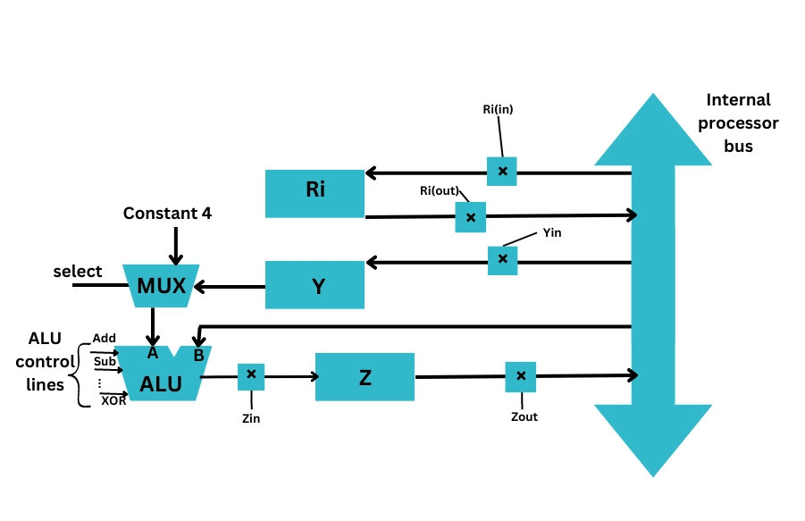
bus transfer using multiplexer

In the above figure

  • Ri is the register. Rin and Rout are its input and output gating signals of Register Ri, respectively. When Rin is set to 1, the data is loaded into the register bus Ri. When Rout is set to 1, the data of the register bus Ri is loaded into the register bus.
  • Z is the register, and Zin and Zout are the input and output gating signals of Register Z.
  • Similarly, Y is the register and Yin and Yout are the input and output gating signals of Register Y.

Bus Transfer using three-state buffer

  • We can also generate a bus system using three-state gates instead of multiplexers.
  • Three State Buffer helps us generate a common bus. 
  • Here the three-state gates are similar to the digital circuit having three gates. Here the first two are similar to having logic 0 and 1. The third gate is in a state of high impedance.
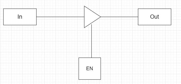
bus transfer using three-state buffer

Figure showing three-state buffer

Memory Transfer

There are two memory operations in memory transfer

  • Read Operation: It is the transfer of the data from memory to the outside environment.
  • Write Operation: It is the transfer of the new data to be stored to the memory. 

Let us have a look at some of the registers and abbreviations used for memory:

  • MBR: MBR stands for memory buffer register. It is also known as (Memory Data Register) MDR. It stores the data being transferred to and from memory.
  • MAR: The Memory Address Register(MAR) is the CPU register used to store the memory’s address at which the data is stored and fetched. It is often represented as AR(Address Register). M represents the memory word.

Read Operation

The transfer of data from the Address Register into the Memory Buffer Register is known as the Read Operation.

The read operation is represented by  MBR ← [AR] M . It states that the Memory Unit M is transferred from [AR] representing Address register to Memory Buffer Register (MBA).

Write Operation

Write Operation is the transfer of new data into the memory. 

The write operation is denoted by [AR] M ← R1. It states that the Memory M from Register R1 is transferred to Address Register([AR]).

Introduction To Microoperation

In computer central processing units, micro-operations (also known as micro-ops or μops, historically also as micro-actions) are detailed low-level instructions used in some designs to implement complex machine instructions.

Usually, micro-operations perform basic operations on data stored in one or more registers, including transferring data between registers or between registers and external buses of the central processing unit (CPU), and performing arithmetic or logical operations on registers. In a typical fetch-decode-execute cycle, each step of a macro-instruction is decomposed during its execution so the CPU determines and steps through a series of micro-operations. The execution of micro-operations is performed under control of the CPU’s control unit, which decides on their execution while performing various optimizations such as reordering, fusion and caching

There are four types of micro-operations:-

  1. Register micro-operations
  2. Arithmetic micro-operations
  3. Logic micro-operations
  4. Shift micro-operations

In this blog, we will discuss arithmetic micro-operations.

Arithmetic Micro-Operations

Arithmetic micro-operations perform operations on the numeric data stored in the registers. 

The basic arithmetic micro-operations are-

  1. Addition
  2. Subtraction
  3. Increment
  4. Decrement
  5. 1’s complement
  6. 2’s complement

Let’s discuss these arithmetic micro-operations one by one.

Addition

The Add arithmetic micro-operation adds the values of the two registers and stores the output in the desired register.

The symbolic notation for the Add arithmetic micro-operation is-

R3 <- R1 + R2

Here, R1 and R2 are the registers whose contents we want to add and,

R3 is the desired register for storing the output.

Note: We can either store the output in another register or the same register, i.e. R1 or R2.

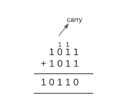
For example, consider the value of register R1 as 1010 and the value of register R2 as 0011. For performing the add arithmetic micro-operation remember the following rules:

  • 0 + 0 = 0
  • 0 + 1 = 1
  • 1 + 0 = 1
  • 1 + 1 = 10 (here, 0 is placed in the result and 1 is transferred as carry to the next column)

If we add R1 and R2, the output will be-
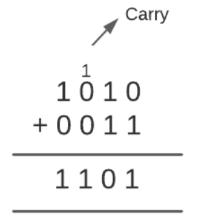
Add Micro Operation

Subtraction

The Subtract arithmetic micro-operation subtracts the values of the two registers and stores the output in the desired register.

The symbolic notation for the Add arithmetic micro-operation is-

R3 <- R1 – R2

Here, R1 and R2 are the registers whose contents we want to subtract and,

R3 is the desired register for storing the output.

Note: We can either store the output in another register or the same register, i.e. R1 or R2.

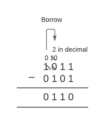
For example, consider the value of register R1 as 1011 and register R2 as 0101. For performing the subtract arithmetic micro-operation remember the following rules:

  • 0 – 0 = 0
  • 0 – 1 = 1 (because 10 is borrowed from next high order digit which is equal to 2 in decimal so 2 – 1 = 1)
  • 1 – 0 = 1
  • 1 – 1 = 0 

If we subtract R2 from R1, the output will be-
Subtract Micro Operation

Besides the above way, there is also an alternate way of doing the arithmetic subtraction. This way includes the use of the 2’s complement.

To subtract the values of two registers, we need to add the first register, the complemented value of the second register and one. 

The symbolic notation is-

R3 <- R1 + R2’ + 1

Here, R1 and R2 are the registers whose contents we want to subtract and,

R3 is the desired register for storing the output.

Using this method, we get the same output as R1 – R2.

Note: We can either store the output in another register or the same register, i.e. R1 or R2.

For example, consider the value of register R1 as 1011 and register R2 as 0101 (same as we take firstly). Now, we will perform subtraction using the alternate method.

First, we will complement the value of the register R2. 0 will be converted to 1 and 1 to 0.

Therefore, the content of R2 will become 1010. 

Second, we will add R2 and 1.
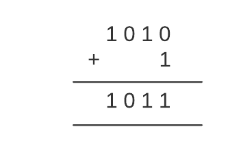
subtraction of arithmetic micro-operations

Finally, we will add R1 and R2.

arithmetic micro-operations subtraction

We will ignore the overflow bit (1 in this case). So, our output will be 0110.

Increment

The Increment arithmetic micro-operation increments the value of a register by 1. This means this operation adds 1 to the value of the given register and stores the output in the desired register.

The symbolic notation for the Increment arithmetic micro-operation is-

R1 <- R1 + 1

Here, R1 is the register whose value we want to increment and,

R1 is also the desired register for storing the output.

Note: We can store the output in another register or the same register.

For example, consider the value of register R1 as 0101. For performing the increment arithmetic micro-operation, we will add 1 to R1.
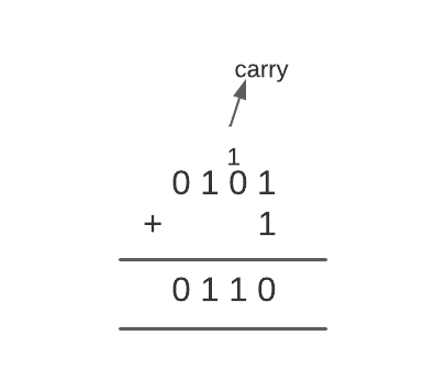
Increment arithmetic micro operation

The Increment arithmetic micro-operations is carried out with the help of a combinational circuit or a binary up-down counter.

Decrement

The Decrement arithmetic micro-operation decreases the value of a register by 1. This means this operation subtracts one from the value of the given register and stores the output in the desired register.

The symbolic notation for the Increment arithmetic micro-operation is-

R1 <- R1 – 1

Here, R1 is the register whose value we want to decrement and,

R1 is also the desired register for storing the output.

For example, consider the value of register R1 as 0101. For performing the decrement arithmetic micro-operation, we will subtract one from R1.
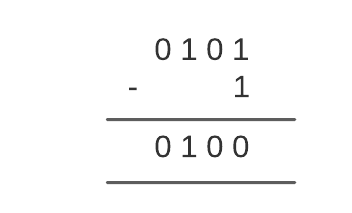
Decrement arithmetic micro operation

The Decrement arithmetic micro-operation is carried out with the help of a combinational circuit or a binary up-down counter.

1’s Complement

The 1’s complement arithmetic micro-operation complements the contents of a register. In this micro-operation, 0 is converted to 1 and 1 is converted to 0. 

The symbolic notation for the 1’s complement arithmetic micro-operation is-

R1 <- R1’

Here, R1 is the register whose value we want to complement and,

R1 is also the desired register for storing the output.

Note: We can store the output in another register or the same register.

For example, consider the value of register R1 as 0101. For performing the 1’s complement arithmetic micro-operation, we will just convert 0 to 1 and 1 to 0.

Therefore, 1’s complement of R1 will be 1010.

2’s Complement

The 2’s complement arithmetic micro-operation first complements the contents of the given register and then adds 1 to it. This micro-operation is also known as Negation.

The symbolic notation for the 2’s complement arithmetic micro-operation is-

R2 <- R2’ + 1

Here, R2 is the register on whose value we want to perform 2’s complement and,

R2 is also the desired register for storing the output.

Note: We can store the output in another register or the same register.

For example, consider the value of register R2 as 0101. For performing the 2’s complement arithmetic micro-operation first, we will find the 1’s complement of R2.

The 1’s complement of R2 will be 1010. Then we will add 1 to it.
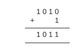
2s complement

The signals that implement these operations propagate through gates in this case, and the result of the process can be transferred into a destination register via a clock pulse immediately after the output signal propagates through the combinational circuit.

Besides the above-described arithmetic micro-operations, there are two more arithmetic micro-operations- multiply and divide. These two operations are valid arithmetic operations, but they are not part of the required set of micro-operations.
A series of add and shift micro-operations are used to perform the multiply micro-operation. 

A series of subtracting and shifting micro-operations are used to complete the divide micro-operation.

The following table shows the symbolic representation of various Arithmetic Micro-operations.

Symbolic Representation Description
R3 ← R1 + R2 The contents of R1 plus R2 are transferred to R3.
R3 ← R1 – R2 The contents of R1 minus R2 are transferred to R3.
R2 ← R2′ Complement the contents of R2(1’s complement).
R2 ← R2′ + 1 2’s complement the contents of R2(negate).
R3 ← R1 + R2′ + 1 R1 plus the 2’s complement of R2(subtraction).
R1 ← R1 + 1 Increment the contents of R1 by one.
R1 ← R1 – 1 Decrement the contents of R1 by one.

 Logic Micro-Operations?

Logic micro-operations are used on the bits of data stored in registers. These micro-operations treat each bit independently and create binary variables from them.

There are a total of 16 micro-operations available. These are-
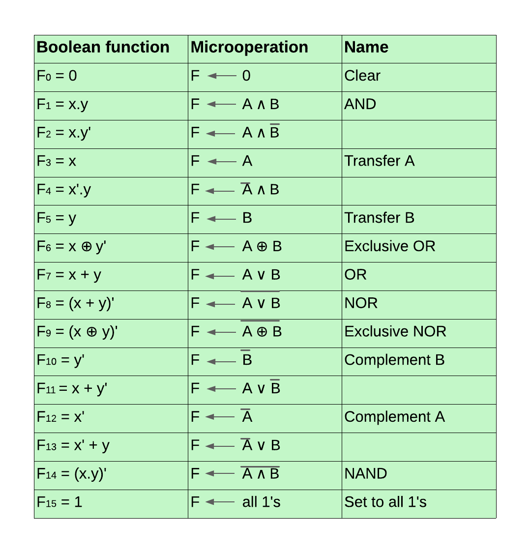
16 micro-operations

Before discussing these logic micro-operations, let’s discuss their truth tables.

The below diagram shows the truth table for all the 16 logic micro-operations mentioned above. Here, x and y are the variables or registers in which the data is stored and F0, F1, ….., F15 are the outputs that occur after performing these logic micro-operations.

Output for Micro Operations

Now, we will discuss these logic micro-operations one by one.

1. Clear

The Clear logic micro-operation is used to clear the register or set the bits of the register to 0. To use this micro-operation, we need to feed 0 to the register. In the above truth table, F0 represents the truth table of Clear logic micro-operation.

For example, F <- 0 means the value of the register F is set to 0 or is cleared. The previous value of register F will be removed.

Boolean expression-

The boolean expression for the Clear logic micro-operation is F0 = 0

2. AND

The AND logic micro-operation performs the logical AND between the bits of the data stored in the two registers. The symbol to represent the logical AND is ∧ . 

Case 1: Both x and y values are true.

In the first case, if the values of both two registers are true then the result of AND operation is 1; else, it is 0. F1 represents the truth table of AND logic micro-operation in the above truth table.

For example, F <- A ∧ B means the registers A and B value will undergo AND micro-operation, and the output will be stored in register F.

Boolean expression-

The boolean expression for the AND logic micro-operation will be F1 = x.y

Case 2: x is true, and y is false.

The logical AND operation we discussed above gives output 1 when both x and y are true. There is also another AND operation which includes x but not y. Also known as inhibition, here for performing the AND operation, the first value is taken from the x variable or register. The second value is taken as the complement of the y variable or register. If the value of the x register is true and of the y register is false, then the result of AND operation is 1; else, it is 0.

F2 represents the truth table of inhibition AND logic micro-operation in the above truth table.

For example, F <- A ∧ B’ means the value of the registers A and complement B will undergo AND micro-operation, and the output will be stored in register F.

Boolean expression-

The boolean expression for the AND logic micro-operation will be F2 = x.y’

Case 3: x is false, and y is true.

The third case of logical AND operation includes y but not x. Also known as inhibition, here for performing the AND operation, the first value is taken as the complement of the x variable or register, and the second value is taken from the y variable or register. If the value of the x register is false and of the y register is true, then the result of AND operation is 1; else, it is 0.

F4 represents the truth table of inhibition AND logic micro-operation in the above truth table.

For example, F <- A’ ∧ B means the value of the complement register A and as it is B will undergo AND micro-operation, and the output will be stored in register F.

Boolean expression-

The boolean expression for the AND logic micro-operation will be F4 = x’.y

3. Transfer A

The Transfer A logic micro-operation transfers the contents of register A (first register) to the output register. 

F3 represents the truth table of Transfer A logic micro-operation in the above truth table. Since there is a transfer of data from the first register to the output register in this micro-operation, its truth table is the same as the taken values of the x variable (0, 0, 1, 1). 

For example, F <- A means the value of register A is moved to register F. The previous value of register F will be removed.

Boolean expression-

The boolean expression for the Transfer A logic micro-operation is F3 = x

4. Transfer B

The Transfer B logic micro-operation transfers the contents of register B (second register) to the output register. 

F5 represents the truth table of Transfer B logic micro-operation in the above truth table. Since there is a transfer of data from the second register to the output register in this micro-operation, its truth table is the same as the taken values of the y variable (0, 1, 0, 1). 

For example, F <- B means the value of register B is moved to register F. The previous value of register F will be removed.

Boolean expression-

The boolean expression for the Transfer B logic micro-operation is F5 = y

5. Exclusive OR

Also known as XOR, this logic micro-operation performs the logical XOR between the data bits stored in the two registers. The logical XOR means either x should be true or y but not both. The symbol to represent the Exclusive OR is ⊕.

F6 represents the truth table of Exclusive OR logic micro-operation in the above truth table. The output will be 1 when either x =1 and y = 0 or x = 0 and y = 1.

For example, F <- A ⊕ B means the registers A and B value will undergo XOR micro-operation, and the output will be stored in register F.

Boolean expression-

The boolean expression for the Exclusive OR logic micro-operation will be F6 = x.y’ + x’.y

6. OR

The OR logic micro-operation performs the logical OR between the data bits stored in the two registers. The symbol to represent the logical OR is ∨.

Case 1: Either x or y or both x and y values are true.

In the first case, if either the value of x register is true and y register is false, or the value of x register is false, and y register is true, or both the values of x and y registers are true, then the result of OR operation is 1 else it is 0. F7 represents the truth table of OR logic micro-operation in the above truth table.

For example, F <- A ∨ B means the registers A and B value will undergo OR micro-operation, and the output will be stored in register F.

Boolean expression-

The boolean expression for the OR logic micro-operation will be F7 = x + y

Case 2: If y, then x else not.

In the second case, the output for 1 follows the condition that

  • If the value of the y register is true, then the value of the x register must be true. If this condition is satisfied, then the output is 1. 
  • If the value of the y register is false, then we don’t need to look for the value of the x register, and the output is 1. 
  • Else the output is 0.  

To perform this logic micro-operation, we need to perform the logical OR of the values of the x register and the complement value of the y register. 

In the above truth table, F11 represents the truth table of this logic micro-operation.

For example, F <- A ∨ B’ means the value of the registers A and complement B will undergo OR micro-operation, and the output will be stored in register F.

Boolean expression-

The boolean expression for this OR logic micro-operation will be F11 = x + y’

Case 3: If x, then y else not.

In the second case, the output for 1 follows the condition that

  • If the value of the x register is true, then the y register’s value must be true. If this condition is satisfied, then the output is 1. 
  • If the value of the x register is 0, then we don’t need to look for the value of the y register, and the output is 1. 
  • Else the output is 0.  

To perform this logic micro-operation, we need to perform the logical OR of the complemented value of the x register and the value of the y register. 

In the above truth table, F13 represents the truth table of this logic micro-operation.

For example, F <- A’ ∨ B means the complemented register A and B value will undergo OR micro-operation, and the output will be stored in register F.

Boolean expression-

The boolean expression for this OR logic micro-operation will be F13 = x’ + y

7. NOR

The NOR logic micro-operation is simply the opposite of OR logic micro-operation. As the name suggests, it is Not OR. The output of OR micro-operation is 1 when the value of either x register or y register or both x and y registers are true. In contrast, in NOR, the output is 0 when the value of either x register or y register or both x and y registers are true, and it is 1 when both x and y registers are false. In the above truth table, F8 represents the truth table of NOR logic micro-operation.

For example, F <- (A ∨ B)’ means the registers A and B value will undergo NOR micro-operation, and the output will be stored in register F.

Boolean expression-

The boolean expression for the Transfer A logic micro-operation is F8 = (x + y)’

8. Exclusive NOR

If we perform the Exclusive NOR micro-operation, the output will be 1 when the values of both the x and y registers will be the same. They can be true or false, but they have to be the same.

F9 represents the truth table of Exclusive NOR logic micro-operation in the above truth table. The output will be 1 when either x = 0 and y = 0 or x = 1 and y = 1.

For example, F <- (A ⊕ B)’ means the registers A and B value will undergo Exclusive NOR micro-operation, and the output will be stored in register F.

Boolean expression-

The boolean expression for the Exclusive NOR logic micro-operation will be F9 = x.y + x’.y’

9. Complement B

The Complement B logic micro-operation transfers the complemented contents of register B (second register) to the output register. First, the content of the register is complemented and then moved to the desired register.

In the above truth table, F10 represents the truth table of Complement B logic micro-operation. Since there is a transfer of complemented data from the second register to the output register in this micro-operation, its truth table is just the opposite of the taken values of the y variable (1, 0, 1, 0). 

For example, F <- B’ means the complemented value of register B is moved to register F. The previous value of register F will be removed.

Boolean expression-

The boolean expression for the Complement B logic micro-operation is F10 = y’

10. Complement A

The Complement A logic micro-operation transfers the complemented contents of register A (first register) to the output register. First, the content of the register is complemented and then moved to the desired register.

F12 represents the truth table of Complement A logic micro-operation in the above truth table. Since there is a transfer of complemented data from the first register to the output register in this micro-operation, its truth table is just the opposite of the taken values of the y variable (1, 1, 0, 0). 

For example, F <- A’ means the complemented value of register A is moved to register F. The previous value of register F will be removed.

Boolean expression-

The boolean expression for the Complement A logic micro-operation is F12 = x’

11. NAND

The NAND logic micro-operation is simply the opposite of AND logic micro-operation. As the name suggests, it is Not AND. The output of AND micro-operation is 1 when the value of both the x register and y register is true. In contrast, in NAND, the output is 0 when the value of both x register and y register is true, and it is 1 when either x is false, or y is false, or both are false. 

In the above truth table, F14 represents the truth table of NAND logic micro-operation.

For example, F <- (A ∧ B)’ means the registers A and B value will undergo NAND micro-operation, and the output will be stored in register F.

Boolean expression-

The boolean expression for the NAND logic micro-operation is F14 = (x.y)’

12. Set to all 1’s

The set to all 1’s logic micro-operations is used to set all the register bits to 1. To use this micro-operation, we just need to feed 1 to the register. In the above truth table, F15 represents the truth table of Set to all 1’s logic micro-operation.

For example, F <- 1 means the value of the register F is set to 1. The previous value of register F will be removed.

Boolean expression-

The boolean expression for the Clear logic micro-operation is F15 = 1

Examples of Logic Micro Operations in Real-World Computing

Logical microoperations are performed on binary data at a hardware level in the processor. Let’s discuss some examples of logical micro-operations in real-world computation.
 

  • Logical microoperations are used in MUX (multiplexers) and DEMUX (Demultiplersers). MUX is used in address decoding, data routing, etc. While DEMUX is used in signal demodulation and functions as a serial-to-parallel converter. 
     
  • Logical microoperations are used in cryptography, image processing, etc., where we need accurate control over the individual bits.
     
  • Logical microoperations, such as shift microoperations, are used in data storage, compression algorithms, and in other areas to use memory effectively.
     
  • They are used in machine learning algorithms for manipulating the data and for making decisions according to the patterns in the dataset. The algorithms are further used in image recognition, voice recognition, natural language processing, etc.
     
  • Logical microoperations are used for masking purposes. The AND microoperation is used to mask bits of a register.
     
  • Logical microoperations are used to build arithmetic circuits such as adders and subtracters. They are formed by the combination of XOR, AND, and OR  for performing subtraction and addition operations.

Advantages of Logic Micro Operations in Processor Design

Below are some of the advantages of logic micro-operations.
 

  • Logical microoperations consume less power. Therefore they help in building low-power consumption systems.
     
  • They are easy to scale and can hold larger amounts of datasets.
     
  • Logical microoperations can reduce the complexity of computations by breaking them into manageable components so that they can be optimized effectively.
     
  • Logic micro-operations are very fast and allow efficient processing of huge amounts of data.
     
  • Logical micro-operations are very flexible and can be combined in multiple ways to perform a wide number of computations. 


Shift Micro-Operations in Computer Architecture?

Shift micro-operations are used when the data is stored in registers. These micro-operations are used for the serial transmission of data. Here, the data bits are shifted from left to right. These micro-operations are also combined with arithmetic and logic micro-operations and data-processing operations.

There are three types of shift micro-operations-

  1. Logical Shift
  2. Arithmetic Shift
  3. Circular Shift

Let’s start with logical shift micro-operation.

Logical Shift

The logical shift micro-operation moves the 0 through the serial input. There are two ways to implement the logical shift.

  1. Logical Shift Left
  2. Logical Shift Right

Let’s discuss both of them one by one.

Logical Shift Left

Each bit in the register is shifted to the left one by one in this shift micro-operation. The most significant bit (MSB) is moved outside the register, and the place of the least significant bit (LSB) is filled with 0. 

For example, in the below data, there are 8 bits 00001010. When we perform a logical shift left on these bits, all these bits will be shifted towards the left. The MSB or the leftmost bit i.e. 0 will be moved outside, and at the rightmost place or LSB, 0 will be inserted as shown below.
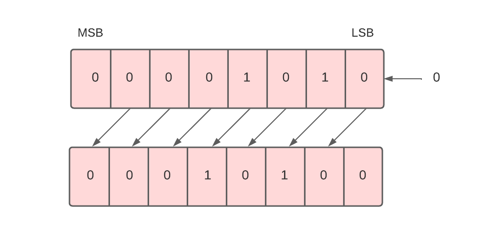
Logical Shift Left

To implement the logical shift left micro-operation, we use the shl symbol.  

For example, R1 -> shl R1.

This command means the 8 bits present in the R1 register will be logically shifted left, and the result will be stored in register R1.

Moreover, the logical shift left microoperation denotes the multiplication of 2. The example we’ve taken above when converted into decimal forms the number 10. And the result after the logical shift operation when converted to decimal forms the number 20. 

Next, we will see the logical shift right micro-operation.

Logical Shift Right

Each bit in the register is shifted to the right one by one in this shift micro-operation. The least significant bit (LSB) is moved outside the register, and the place of the most significant bit (MSB) is filled with 0. 

For example, in the below data, there are 8 bits 00000101. When we perform a logical shift right on these bits, all these bits will be shifted towards the right. The LSB or the rightmost bit i.e. 1 will be moved outside, and at the leftmost place or MSB, 0 will be inserted as shown below.
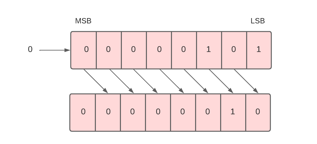
Logical Shift Right

To implement the logical shift right micro-operation, we use the shr symbol.  

For example, R1 -> shr R1.

This command means the 8 bits present in the R1 register will be logically shifted right, and the result will be stored in register R1.

Logical right shift micro-operation generally denotes division by 2. The inputted bits when converted into decimal form the number 5. And the outcome when converted into decimal forms the number 2. 

Next, we will study arithmetic shift micro-operation.

Arithmetic Shift

The arithmetic shift micro-operation moves the signed binary number either to the left or to the right position. There are two ways to implement the arithmetic shift.

  1. Arithmetic Shift Left
  2. Arithmetic Shift Right

Let’s discuss both of them one by one.

Arithmetic Shift Left

The arithmetic shift left micro-operation is the same as the logical shift left micro-operation. Each bit in the register is shifted to the left one by one in this shift micro-operation. The most significant bit (MSB) is moved outside the register, and the place of the least significant bit (LSB) is filled with 0. 

For example, in the below data, there are 8 bits 00100011. When we perform the arithmetic shift left on these bits, all these bits will be shifted towards the left. The MSB or the leftmost bit i.e. 0 will be moved outside, and at the rightmost place or LSB, 0 will be inserted as shown below.
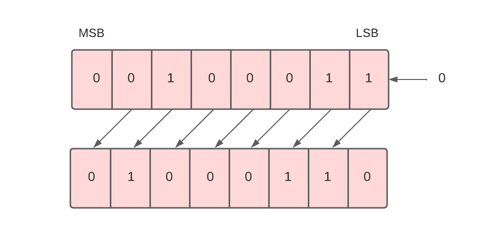
Arithmetic Shift Left

The given binary number (00100011) represents 35 in the decimal system. And the binary number after logical shift left (01000110) represents 70 in a decimal system. Since 35 * 2 = 70. Therefore, we can say that the arithmetic shift left multiplies the number by 2.

To implement the arithmetic shift left micro-operation, we use the ashl symbol.  

For example, R1 -> ashl R1.

This command means the 8 bits present in the R1 register will be arithmetic shifted left, and the result will be stored in register R1.

Arithmetic Shift Right

Each bit in the register is shifted to the right one by one in this shift micro-operation. The least significant bit (LSB) is moved outside the register, and the place of the most significant bit (MSB) is filled with the previous value of MSB. 

For example, in the below data, there are 8 bits 10100011. When we perform an arithmetic shift right on these bits, all these bits will be shifted towards the right. The LSB or the rightmost bit i.e. 1 will be moved outside, and at the leftmost place or MSB, the previous MSB value, i.e. 1, will be inserted as shown below.
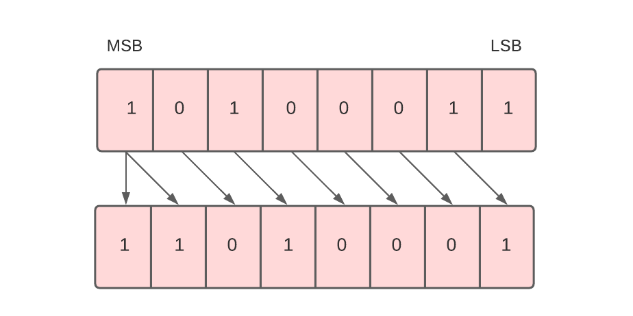
Arithmetic Shift Right

Arithmetic right shift divides the number by 2.

To implement the arithmetic shift right micro-operation, we use the ashr symbol.  

For example, R1 -> ashr R1.

This command means the 8 bits present in the R1 register will be arithmetic shifted right, and the result will be stored in register R1.

Next, we will study circular shift micro-operation.

Circular Shift

The circular shift, also known as the rotate shift, moves the bits in the register’s sequence around both ends, thus ensuring no loss of information. There are two ways to implement the circular shift.

  1. Circular Shift Left
  2. Circular Shift Right

Let’s discuss both of them one by one.

Circular Shift Left

Each bit in the register is shifted to the left one by one in this shift micro-operation. After shifting, the least significant bit (LSB) place becomes empty, so it is filled with the value at the most significant bit (MSB). 

For example, in the below data, there are 8 bits 00010100. When we perform a circular shift left on these bits, all these bits will be shifted towards the left. The MSB or the leftmost bit i.e. 0 will be placed at the rightmost place or LSB as shown below.
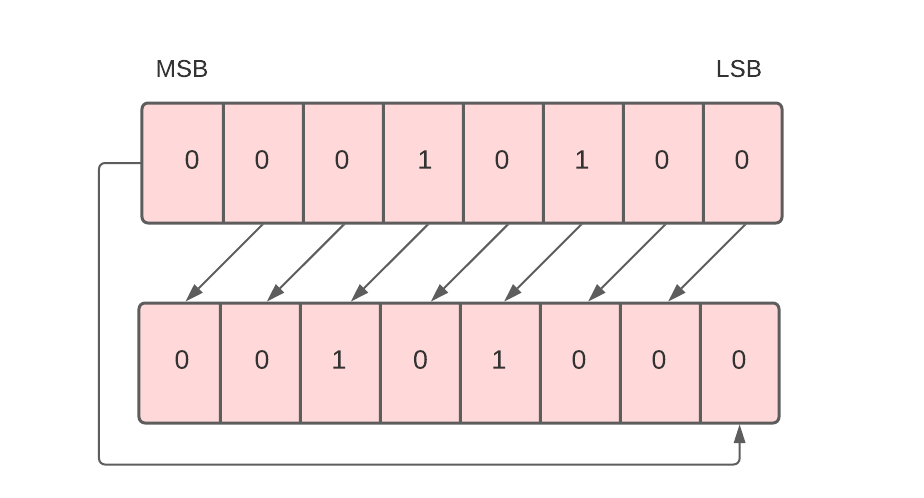
Circular Shift Left

To implement the circular shift left micro-operation, we use the cil symbol.  

For example, R1 -> cil R1.

This command means the 8 bits present in the R1 register will be circular shifted left, and the result will be stored in register R1.

Next, we will discuss circular shift right micro-operation.

Circular Shift Right

Each bit in the register is shifted to the right one by one in this shift micro-operation. After shifting, the most significant bit (MSB) place becomes empty, so it is filled with the value at the least significant bit (LSB). 

For example, in the below data, there are 8 bits 00010100. When we perform a circular shift right on these bits, all these bits will be shifted towards the right. The LSB or the leftmost bit, i.e. 0, will be placed at the rightmost place or MSB.
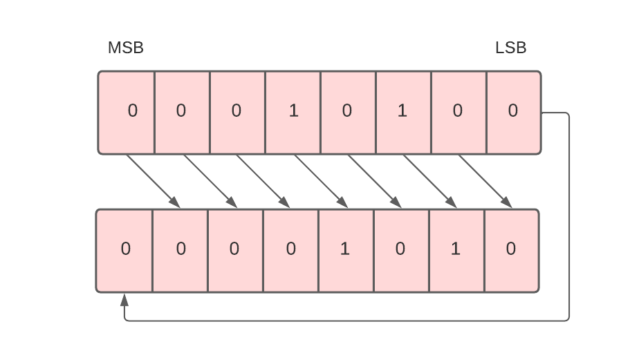
Circular Shift Right

To implement the circular shift right micro-operation, we use the cir symbol.  

For example, R1 -> cir R1.

This command means the 8 bits present in the R1 register will be circular shifted right, and the result will be stored in register R1.

Design Of Control Unit

Central Processing Unit is the most important component of a computer system. A control unit is a part of the CPU. A control unit controls the operations of all parts of the computer but it does not carry out any data processing operations.

What is a Control Unit?

The Control Unit is the part of the computer’s central processing unit (CPU), which directs the operation of the processor. It was included as part of the Von Neumann Architecture by John von Neumann. It is the responsibility of the control unit to tell the computer’s memory, arithmetic/logic unit, and input and output devices how to respond to the instructions that have been sent to the processor. It fetches internal instructions of the programs from the main memory to the processor instruction register, and based on this register contents, the control unit generates a control signal that supervises the execution of these instructions. A control unit works by receiving input information which it converts into control signals, which are then sent to the central processor. The computer’s processor then tells the attached hardware what operations to perform. The functions that a control unit performs are dependent on the type of CPU because the architecture of the CPU varies from manufacturer to manufacturer.


Examples of devices that require a CU are:

  • Control Processing Units(CPUs)
  • Graphics Processing Units(GPUs)

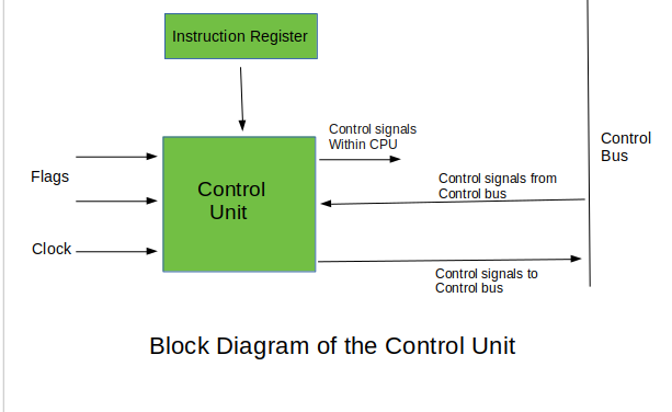
what is control unit?

Functions of the Control Unit

  • It coordinates the sequence of data movements into, out of, and between a processor’s many sub-units.
  • It interprets instructions.
  • It controls data flow inside the processor.
  • It receives external instructions or commands to which it converts to sequence of control signals.
  • It controls many execution units(i.e. ALU, data buffers and registers) contained within a CPU.
  • It also handles multiple tasks, such as fetching, decoding, execution handling and storing results.

Types of Control Unit

There are two types of control units:

  • Hardwired
  • Micro programmable control unit.

Hardwired Control Unit

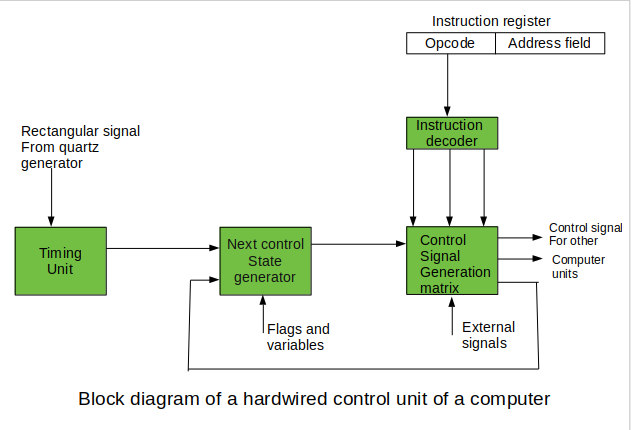
In the Hardwired control unit, the control signals that are important for instruction execution control are generated by specially designed hardware logical circuits, in which we can not modify the signal generation method without physical change of the circuit structure. The operation code of an instruction contains the basic data for control signal generation. In the instruction decoder, the operation code is decoded. The instruction decoder constitutes a set of many decoders that decode different fields of the instruction opcode.

hardwired control unit

Control signals for an instruction execution have to be generated not in a single time point but during the entire time interval that corresponds to the instruction execution cycle. Following the structure of this cycle, the suitable sequence of internal states is organized in the control unit. A number of signals generated by the control signal generator matrix are sent back to inputs of the next control state generator matrix.


Micro Programmable control unit

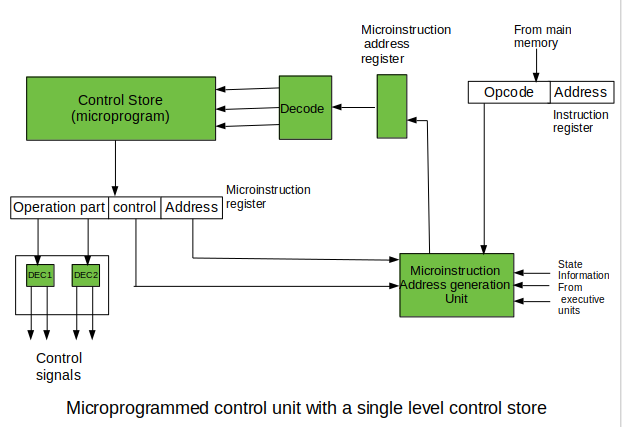
The fundamental difference between these unit structures and the structure of the hardwired control unit is the existence of the control store that is used for storing words containing encoded control signals mandatory for instruction execution. In microprogrammed control units, subsequent instruction words are fetched into the instruction register in a normal way. However, the operation code of each instruction is not directly decoded to enable immediate control signal generation but it comprises the initial address of a microprogram contained in the control store.

  • With a single-level control store: In this, the instruction opcode from the instruction register is sent to the control store address register. Based on this address, the first microinstruction of a microprogram that interprets execution of this instruction is read to the microinstruction register. This microinstruction contains in its operation part encoded control signals, normally as few bit fields. In a set microinstruction field decoders, the fields are decoded. The microinstruction also contains the address of the next microinstruction of the given instruction microprogram and a control field used to control activities of the microinstruction address generator. With single level control storeThe last mentioned field decides the addressing mode (addressing operation) to be applied to the address embedded in the ongoing microinstruction. In microinstructions along with conditional addressing mode, this address is refined by using the processor condition flags that represent the status of computations in the current program. The last microinstruction in the instruction of the given microprogram is the microinstruction that fetches the next instruction from the main memory to the instruction register.
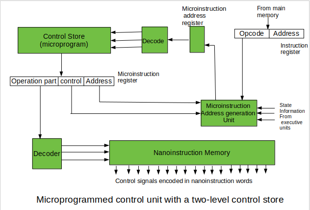
  • With a two-level control store: In this, in a control unit with a two-level control store, besides the control memory for microinstructions, a nano-instruction memory is included. In such a control unit, microinstructions do not contain encoded control signals. The operation part of microinstructions contains the address of the word in the nano-instruction memory, which contains encoded control signals. The nano-instruction memory contains all combinations of control signals that appear in microprograms that interpret the complete instruction set of a given computer, written once in the form of nano-instructions. WIth two level control storeIn this way, unnecessary storing of the same operation parts of microinstructions is avoided. In this case, microinstruction word can be much shorter than with the single level control store. It gives a much smaller size in bits of the microinstruction memory and, as a result, a much smaller size of the entire control memory. The microinstruction memory contains the control for selection of consecutive microinstructions, while those control signals are generated at the basis of nano-instructions. In nano-instructions, control signals are frequently encoded using 1 bit/ 1 signal method that eliminates decoding.

Advantages of a Well-Designed Control Unit

  • Efficient instruction execution: A well-designed control unit can execute instructions more efficiently by optimizing the instruction pipeline and minimizing the number of clock cycles required for each instruction.
  • Improved performance: A well-designed control unit can improve the performance of the CPU by increasing the clock speed, reducing the latency, and improving the throughput.
  • Support for complex instructions: A well-designed control unit can support complex instructions that require multiple operations, reducing the number of instructions required to execute a program.
  • Improved reliability: A well-designed control unit can improve the reliability of the CPU by detecting and correcting errors, such as memory errors and pipeline stalls.
  • Lower power consumption: A well-designed control unit can reduce power consumption by optimizing the use of resources, such as registers and memory, and reducing the number of clock cycles required for each instruction.
  • Better branch prediction: A well-designed control unit can improve branch prediction accuracy, reducing the number of branch mispredictions and improving performance.
  • Improved scalability: A well-designed control unit can improve the scalability of the CPU, allowing it to handle larger and more complex workloads.
  • Better support for parallelism: A well-designed control unit can better support parallelism, allowing the CPU to execute multiple instructions simultaneously and improve overall performance.
  • Improved security: A well-designed control unit can improve the security of the CPU by implementing security features such as address space layout randomization and data execution prevention.
  • Lower cost: A well-designed control unit can reduce the cost of the CPU by minimizing the number of components required and improving manufacturing efficiency.

Disadvantages of a Poorly-Designed Control Unit

  • Reduced performance: A poorly-designed control unit can reduce the performance of the CPU by introducing pipeline stalls, increasing the latency, and reducing the throughput.
  • Increased complexity: A poorly-designed control unit can increase the complexity of the CPU, making it harder to design, test, and maintain.
  • Higher power consumption: A poorly-designed control unit can increase power consumption by inefficiently using resources, such as registers and memory, and requiring more clock cycles for each instruction.
  • Reduced reliability: A poorly-designed control unit can reduce the reliability of the CPU by introducing errors, such as memory errors and pipeline stalls.
  • Limitations on instruction set: A poorly-designed control unit may limit the instruction set of the CPU, making it harder to execute complex instructions and limiting the functionality of the CPU.
  • Inefficient use of resources: A poorly-designed control unit may inefficiently use resources such as registers and memory, leading to wasted resources and reduced performance.
  • Limited scalability: A poorly-designed control unit may limit the scalability of the CPU, making it harder to handle larger and more complex workloads.
  • Poor support for parallelism: A poorly-designed control unit may limit the ability of the CPU to support parallelism, reducing the overall performance of the system.
  • Security vulnerabilities: A poorly-designed control unit may introduce security vulnerabilities, such as buffer overflows or code injection attacks.
  • Higher cost: A poorly-designed control unit may increase the cost of the CPU by requiring additional components or increasing the manufacturing complexity.