

In symbolic notation, it is used to describe the micro-operations transfer among registers. It is a kind of intermediate representation (IR) that is very close to assembly language, such as that which is used in a compiler.The term “Register Transfer” can perform micro-operations and transfer the result of operation to the same or other register.
Micro-operations :
The operation executed on the data store in registers are called micro-operations. They are detailed low-level instructions used in some designs to implement complex machine instructions.
Register Transfer :
The information transformed from one register to another register is represented in symbolic form by replacement operator is called Register Transfer.
Replacement Operator :
In the statement, R2 <- R1, <- acts as a replacement operator. This statement defines the transfer of content of register R1 into register R2.
There are various methods of RTL –
- General way of representing a register is by the name of the register enclosed in a rectangular box as shown in (a).
- Register is numbered in a sequence of 0 to (n-1) as shown in (b).
- The numbering of bits in a register can be marked on the top of the box as shown in (c).
- A 16-bit register PC is divided into 2 parts- Bits (0 to 7) are assigned with lower byte of 16-bit address and bits (8 to 15) are assigned with higher bytes of 16-bit address as shown in (d).

Basic symbols of RTL :
| Symbol | Description | Example |
|---|---|---|
| Letters and Numbers | Denotes a Register | MAR, R1, R2 |
| ( ) | Denotes a part of register |
R1(8-bit) R1(0-7) |
| <- | Denotes a transfer of information | R2 <- R1 |
| , | Specify two micro-operations of Register Transfer |
R1 <- R2 R2 <- R1 |
| : | Denotes conditional operations |
P : R2 <- R1 if P=1 |
| Naming Operator (:=) | Denotes another name for an already existing register/alias | Ra := R1 |
Register Transfer Operations:
The operation performed on the data stored in the registers are referred to as register transfer operations.
There are different types of register transfer operations:
1. Simple Transfer – R2 <- R1
The content of R1 are copied into R2 without affecting the content of R1. It is an unconditional type of transfer operation.
2. Conditional Transfer –

It indicates that if P=1, then the content of R1 is transferred to R2. It is a unidirectional operation.
3. Simultaneous Operations –
If 2 or more operations are to occur simultaneously then they are separated with comma (,).

If the control function P=1, then load the content of R1 into R2 and at the same clock load the content of R2 into R1.
Bus and Memory Transfer
Bus Transfer is the most efficient way to transfer data. The data transferred in the bus transfer is collected using bus lines. Similarly, the transfer of data from the memory unit to the outside environment and vice versa is known as memory transfer.
To brush up on your knowledge of the circuit, you can read the article combinational circuit on Coding Ninjas Studio.
In this article, you will learn about bus and memory transfer.
Bus Transfer
- In a digital system of registers, a path must be provided to move information.
- Suppose separate lines are used between each register and all other registers in the system. In that case, the number of wires connecting all of the registers will be excessive because we are connecting each register with another register.
- A bus structure will not require an excessive connection. Thus it is very useful in transferring information.
- A bus is made up of a collection of common lines, one for each bit of a register, that are used to transfer binary data one by one.
There are two methods in bus transfer:
- Bus transfer using Multiplexer
- Bus transfer using Three states bus buffer
Bus Transfer using multiplexer
We can generate a common bus using a multiplexer. Multiplexer helps us choose the source register to put the binary data on the bus. Control Signal controls the input and output gating.
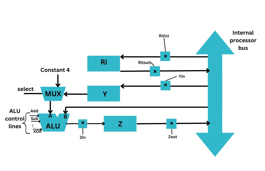
In the above figure
- Ri is the register. Rin and Rout are its input and output gating signals of Register Ri, respectively. When Rin is set to 1, the data is loaded into the register bus Ri. When Rout is set to 1, the data of the register bus Ri is loaded into the register bus.
- Z is the register, and Zin and Zout are the input and output gating signals of Register Z.
- Similarly, Y is the register and Yin and Yout are the input and output gating signals of Register Y.
Bus Transfer using three-state buffer
- We can also generate a bus system using three-state gates instead of multiplexers.
- Three State Buffer helps us generate a common bus.
- Here the three-state gates are similar to the digital circuit having three gates. Here the first two are similar to having logic 0 and 1. The third gate is in a state of high impedance.
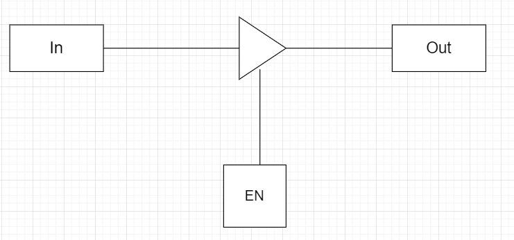
Figure showing three-state buffer
Memory Transfer
There are two memory operations in memory transfer
- Read Operation: It is the transfer of the data from memory to the outside environment.
- Write Operation: It is the transfer of the new data to be stored to the memory.
Let us have a look at some of the registers and abbreviations used for memory:
- MBR: MBR stands for memory buffer register. It is also known as (Memory Data Register) MDR. It stores the data being transferred to and from memory.
- MAR: The Memory Address Register(MAR) is the CPU register used to store the memory’s address at which the data is stored and fetched. It is often represented as AR(Address Register). M represents the memory word.
Read Operation
The transfer of data from the Address Register into the Memory Buffer Register is known as the Read Operation.
The read operation is represented by MBR ← [AR] M . It states that the Memory Unit M is transferred from [AR] representing Address register to Memory Buffer Register (MBA).
Write Operation
Write Operation is the transfer of new data into the memory.
The write operation is denoted by [AR] M ← R1. It states that the Memory M from Register R1 is transferred to Address Register([AR]).
Introduction To Microoperation
In computer central processing units, micro-operations (also known as micro-ops or μops, historically also as micro-actions) are detailed low-level instructions used in some designs to implement complex machine instructions.
Usually, micro-operations perform basic operations on data stored in one or more registers, including transferring data between registers or between registers and external buses of the central processing unit (CPU), and performing arithmetic or logical operations on registers. In a typical fetch-decode-execute cycle, each step of a macro-instruction is decomposed during its execution so the CPU determines and steps through a series of micro-operations. The execution of micro-operations is performed under control of the CPU’s control unit, which decides on their execution while performing various optimizations such as reordering, fusion and caching
There are four types of micro-operations:-
- Register micro-operations
- Arithmetic micro-operations
- Logic micro-operations
- Shift micro-operations
In this blog, we will discuss arithmetic micro-operations.
Arithmetic Micro-Operations
Arithmetic micro-operations perform operations on the numeric data stored in the registers.
The basic arithmetic micro-operations are-
- Addition
- Subtraction
- Increment
- Decrement
- 1’s complement
- 2’s complement
Let’s discuss these arithmetic micro-operations one by one.
Addition
The Add arithmetic micro-operation adds the values of the two registers and stores the output in the desired register.
The symbolic notation for the Add arithmetic micro-operation is-
R3 <- R1 + R2
Here, R1 and R2 are the registers whose contents we want to add and,
R3 is the desired register for storing the output.
Note: We can either store the output in another register or the same register, i.e. R1 or R2.
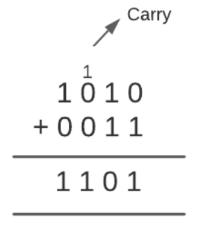
For example, consider the value of register R1 as 1010 and the value of register R2 as 0011. For performing the add arithmetic micro-operation remember the following rules:
- 0 + 0 = 0
- 0 + 1 = 1
- 1 + 0 = 1
- 1 + 1 = 10 (here, 0 is placed in the result and 1 is transferred as carry to the next column)
If we add R1 and R2, the output will be-
Subtraction
The Subtract arithmetic micro-operation subtracts the values of the two registers and stores the output in the desired register.
The symbolic notation for the Add arithmetic micro-operation is-
R3 <- R1 – R2
Here, R1 and R2 are the registers whose contents we want to subtract and,
R3 is the desired register for storing the output.
Note: We can either store the output in another register or the same register, i.e. R1 or R2.
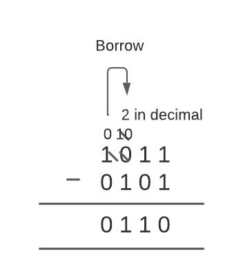
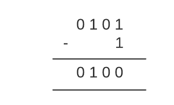
For example, consider the value of register R1 as 1011 and register R2 as 0101. For performing the subtract arithmetic micro-operation remember the following rules:
- 0 – 0 = 0
- 0 – 1 = 1 (because 10 is borrowed from next high order digit which is equal to 2 in decimal so 2 – 1 = 1)
- 1 – 0 = 1
- 1 – 1 = 0
If we subtract R2 from R1, the output will be-
Besides the above way, there is also an alternate way of doing the arithmetic subtraction. This way includes the use of the 2’s complement.
To subtract the values of two registers, we need to add the first register, the complemented value of the second register and one.
The symbolic notation is-
R3 <- R1 + R2’ + 1
Here, R1 and R2 are the registers whose contents we want to subtract and,
R3 is the desired register for storing the output.
Using this method, we get the same output as R1 – R2.
Note: We can either store the output in another register or the same register, i.e. R1 or R2.
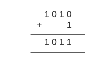
For example, consider the value of register R1 as 1011 and register R2 as 0101 (same as we take firstly). Now, we will perform subtraction using the alternate method.
First, we will complement the value of the register R2. 0 will be converted to 1 and 1 to 0.
Therefore, the content of R2 will become 1010.
Second, we will add R2 and 1.
Finally, we will add R1 and R2.
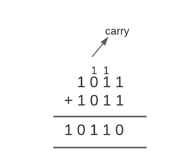
We will ignore the overflow bit (1 in this case). So, our output will be 0110.
Increment
The Increment arithmetic micro-operation increments the value of a register by 1. This means this operation adds 1 to the value of the given register and stores the output in the desired register.
The symbolic notation for the Increment arithmetic micro-operation is-
R1 <- R1 + 1
Here, R1 is the register whose value we want to increment and,
R1 is also the desired register for storing the output.
Note: We can store the output in another register or the same register.
For example, consider the value of register R1 as 0101. For performing the increment arithmetic micro-operation, we will add 1 to R1.
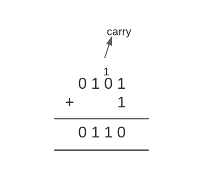
The Increment arithmetic micro-operations is carried out with the help of a combinational circuit or a binary up-down counter.
Decrement
The Decrement arithmetic micro-operation decreases the value of a register by 1. This means this operation subtracts one from the value of the given register and stores the output in the desired register.
The symbolic notation for the Increment arithmetic micro-operation is-
R1 <- R1 – 1
Here, R1 is the register whose value we want to decrement and,
R1 is also the desired register for storing the output.
For example, consider the value of register R1 as 0101. For performing the decrement arithmetic micro-operation, we will subtract one from R1.
The Decrement arithmetic micro-operation is carried out with the help of a combinational circuit or a binary up-down counter.
1’s Complement
The 1’s complement arithmetic micro-operation complements the contents of a register. In this micro-operation, 0 is converted to 1 and 1 is converted to 0.
The symbolic notation for the 1’s complement arithmetic micro-operation is-
R1 <- R1’
Here, R1 is the register whose value we want to complement and,
R1 is also the desired register for storing the output.
Note: We can store the output in another register or the same register.
For example, consider the value of register R1 as 0101. For performing the 1’s complement arithmetic micro-operation, we will just convert 0 to 1 and 1 to 0.
Therefore, 1’s complement of R1 will be 1010.
2’s Complement
The 2’s complement arithmetic micro-operation first complements the contents of the given register and then adds 1 to it. This micro-operation is also known as Negation.
The symbolic notation for the 2’s complement arithmetic micro-operation is-
R2 <- R2’ + 1
Here, R2 is the register on whose value we want to perform 2’s complement and,
R2 is also the desired register for storing the output.
Note: We can store the output in another register or the same register.
For example, consider the value of register R2 as 0101. For performing the 2’s complement arithmetic micro-operation first, we will find the 1’s complement of R2.
The 1’s complement of R2 will be 1010. Then we will add 1 to it.

The signals that implement these operations propagate through gates in this case, and the result of the process can be transferred into a destination register via a clock pulse immediately after the output signal propagates through the combinational circuit.
Besides the above-described arithmetic micro-operations, there are two more arithmetic micro-operations- multiply and divide. These two operations are valid arithmetic operations, but they are not part of the required set of micro-operations.
A series of add and shift micro-operations are used to perform the multiply micro-operation.
A series of subtracting and shifting micro-operations are used to complete the divide micro-operation.
The following table shows the symbolic representation of various Arithmetic Micro-operations.
| Symbolic Representation | Description |
| R3 ← R1 + R2 | The contents of R1 plus R2 are transferred to R3. |
| R3 ← R1 – R2 | The contents of R1 minus R2 are transferred to R3. |
| R2 ← R2′ | Complement the contents of R2(1’s complement). |
| R2 ← R2′ + 1 | 2’s complement the contents of R2(negate). |
| R3 ← R1 + R2′ + 1 | R1 plus the 2’s complement of R2(subtraction). |
| R1 ← R1 + 1 | Increment the contents of R1 by one. |
| R1 ← R1 – 1 | Decrement the contents of R1 by one. |
Logic Micro-Operations?
Logic micro-operations are used on the bits of data stored in registers. These micro-operations treat each bit independently and create binary variables from them.
There are a total of 16 micro-operations available. These are-
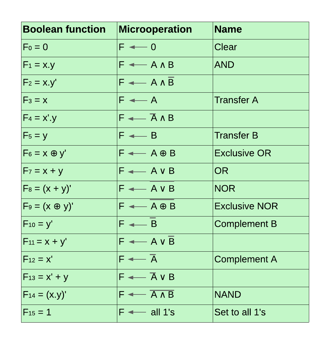
Before discussing these logic micro-operations, let’s discuss their truth tables.
The below diagram shows the truth table for all the 16 logic micro-operations mentioned above. Here, x and y are the variables or registers in which the data is stored and F0, F1, ….., F15 are the outputs that occur after performing these logic micro-operations.

Now, we will discuss these logic micro-operations one by one.
1. Clear
The Clear logic micro-operation is used to clear the register or set the bits of the register to 0. To use this micro-operation, we need to feed 0 to the register. In the above truth table, F0 represents the truth table of Clear logic micro-operation.
For example, F <- 0 means the value of the register F is set to 0 or is cleared. The previous value of register F will be removed.
Boolean expression-
The boolean expression for the Clear logic micro-operation is F0 = 0
2. AND
The AND logic micro-operation performs the logical AND between the bits of the data stored in the two registers. The symbol to represent the logical AND is ∧ .
Case 1: Both x and y values are true.
In the first case, if the values of both two registers are true then the result of AND operation is 1; else, it is 0. F1 represents the truth table of AND logic micro-operation in the above truth table.
For example, F <- A ∧ B means the registers A and B value will undergo AND micro-operation, and the output will be stored in register F.
Boolean expression-
The boolean expression for the AND logic micro-operation will be F1 = x.y
Case 2: x is true, and y is false.
The logical AND operation we discussed above gives output 1 when both x and y are true. There is also another AND operation which includes x but not y. Also known as inhibition, here for performing the AND operation, the first value is taken from the x variable or register. The second value is taken as the complement of the y variable or register. If the value of the x register is true and of the y register is false, then the result of AND operation is 1; else, it is 0.
F2 represents the truth table of inhibition AND logic micro-operation in the above truth table.
For example, F <- A ∧ B’ means the value of the registers A and complement B will undergo AND micro-operation, and the output will be stored in register F.
Boolean expression-
The boolean expression for the AND logic micro-operation will be F2 = x.y’
Case 3: x is false, and y is true.
The third case of logical AND operation includes y but not x. Also known as inhibition, here for performing the AND operation, the first value is taken as the complement of the x variable or register, and the second value is taken from the y variable or register. If the value of the x register is false and of the y register is true, then the result of AND operation is 1; else, it is 0.
F4 represents the truth table of inhibition AND logic micro-operation in the above truth table.
For example, F <- A’ ∧ B means the value of the complement register A and as it is B will undergo AND micro-operation, and the output will be stored in register F.
Boolean expression-
The boolean expression for the AND logic micro-operation will be F4 = x’.y
3. Transfer A
The Transfer A logic micro-operation transfers the contents of register A (first register) to the output register.
F3 represents the truth table of Transfer A logic micro-operation in the above truth table. Since there is a transfer of data from the first register to the output register in this micro-operation, its truth table is the same as the taken values of the x variable (0, 0, 1, 1).
For example, F <- A means the value of register A is moved to register F. The previous value of register F will be removed.
Boolean expression-
The boolean expression for the Transfer A logic micro-operation is F3 = x
4. Transfer B
The Transfer B logic micro-operation transfers the contents of register B (second register) to the output register.
F5 represents the truth table of Transfer B logic micro-operation in the above truth table. Since there is a transfer of data from the second register to the output register in this micro-operation, its truth table is the same as the taken values of the y variable (0, 1, 0, 1).
For example, F <- B means the value of register B is moved to register F. The previous value of register F will be removed.
Boolean expression-
The boolean expression for the Transfer B logic micro-operation is F5 = y
5. Exclusive OR
Also known as XOR, this logic micro-operation performs the logical XOR between the data bits stored in the two registers. The logical XOR means either x should be true or y but not both. The symbol to represent the Exclusive OR is ⊕.
F6 represents the truth table of Exclusive OR logic micro-operation in the above truth table. The output will be 1 when either x =1 and y = 0 or x = 0 and y = 1.
For example, F <- A ⊕ B means the registers A and B value will undergo XOR micro-operation, and the output will be stored in register F.
Boolean expression-
The boolean expression for the Exclusive OR logic micro-operation will be F6 = x.y’ + x’.y
6. OR
The OR logic micro-operation performs the logical OR between the data bits stored in the two registers. The symbol to represent the logical OR is ∨.
Case 1: Either x or y or both x and y values are true.
In the first case, if either the value of x register is true and y register is false, or the value of x register is false, and y register is true, or both the values of x and y registers are true, then the result of OR operation is 1 else it is 0. F7 represents the truth table of OR logic micro-operation in the above truth table.
For example, F <- A ∨ B means the registers A and B value will undergo OR micro-operation, and the output will be stored in register F.
Boolean expression-
The boolean expression for the OR logic micro-operation will be F7 = x + y
Case 2: If y, then x else not.
In the second case, the output for 1 follows the condition that
- If the value of the y register is true, then the value of the x register must be true. If this condition is satisfied, then the output is 1.
- If the value of the y register is false, then we don’t need to look for the value of the x register, and the output is 1.
- Else the output is 0.
To perform this logic micro-operation, we need to perform the logical OR of the values of the x register and the complement value of the y register.
In the above truth table, F11 represents the truth table of this logic micro-operation.
For example, F <- A ∨ B’ means the value of the registers A and complement B will undergo OR micro-operation, and the output will be stored in register F.
Boolean expression-
The boolean expression for this OR logic micro-operation will be F11 = x + y’
Case 3: If x, then y else not.
In the second case, the output for 1 follows the condition that
- If the value of the x register is true, then the y register’s value must be true. If this condition is satisfied, then the output is 1.
- If the value of the x register is 0, then we don’t need to look for the value of the y register, and the output is 1.
- Else the output is 0.
To perform this logic micro-operation, we need to perform the logical OR of the complemented value of the x register and the value of the y register.
In the above truth table, F13 represents the truth table of this logic micro-operation.
For example, F <- A’ ∨ B means the complemented register A and B value will undergo OR micro-operation, and the output will be stored in register F.
Boolean expression-
The boolean expression for this OR logic micro-operation will be F13 = x’ + y
7. NOR
The NOR logic micro-operation is simply the opposite of OR logic micro-operation. As the name suggests, it is Not OR. The output of OR micro-operation is 1 when the value of either x register or y register or both x and y registers are true. In contrast, in NOR, the output is 0 when the value of either x register or y register or both x and y registers are true, and it is 1 when both x and y registers are false. In the above truth table, F8 represents the truth table of NOR logic micro-operation.
For example, F <- (A ∨ B)’ means the registers A and B value will undergo NOR micro-operation, and the output will be stored in register F.
Boolean expression-
The boolean expression for the Transfer A logic micro-operation is F8 = (x + y)’
8. Exclusive NOR
If we perform the Exclusive NOR micro-operation, the output will be 1 when the values of both the x and y registers will be the same. They can be true or false, but they have to be the same.
F9 represents the truth table of Exclusive NOR logic micro-operation in the above truth table. The output will be 1 when either x = 0 and y = 0 or x = 1 and y = 1.
For example, F <- (A ⊕ B)’ means the registers A and B value will undergo Exclusive NOR micro-operation, and the output will be stored in register F.
Boolean expression-
The boolean expression for the Exclusive NOR logic micro-operation will be F9 = x.y + x’.y’
9. Complement B
The Complement B logic micro-operation transfers the complemented contents of register B (second register) to the output register. First, the content of the register is complemented and then moved to the desired register.
In the above truth table, F10 represents the truth table of Complement B logic micro-operation. Since there is a transfer of complemented data from the second register to the output register in this micro-operation, its truth table is just the opposite of the taken values of the y variable (1, 0, 1, 0).
For example, F <- B’ means the complemented value of register B is moved to register F. The previous value of register F will be removed.
Boolean expression-
The boolean expression for the Complement B logic micro-operation is F10 = y’
10. Complement A
The Complement A logic micro-operation transfers the complemented contents of register A (first register) to the output register. First, the content of the register is complemented and then moved to the desired register.
F12 represents the truth table of Complement A logic micro-operation in the above truth table. Since there is a transfer of complemented data from the first register to the output register in this micro-operation, its truth table is just the opposite of the taken values of the y variable (1, 1, 0, 0).
For example, F <- A’ means the complemented value of register A is moved to register F. The previous value of register F will be removed.
Boolean expression-
The boolean expression for the Complement A logic micro-operation is F12 = x’
11. NAND
The NAND logic micro-operation is simply the opposite of AND logic micro-operation. As the name suggests, it is Not AND. The output of AND micro-operation is 1 when the value of both the x register and y register is true. In contrast, in NAND, the output is 0 when the value of both x register and y register is true, and it is 1 when either x is false, or y is false, or both are false.
In the above truth table, F14 represents the truth table of NAND logic micro-operation.
For example, F <- (A ∧ B)’ means the registers A and B value will undergo NAND micro-operation, and the output will be stored in register F.
Boolean expression-
The boolean expression for the NAND logic micro-operation is F14 = (x.y)’
12. Set to all 1’s
The set to all 1’s logic micro-operations is used to set all the register bits to 1. To use this micro-operation, we just need to feed 1 to the register. In the above truth table, F15 represents the truth table of Set to all 1’s logic micro-operation.
For example, F <- 1 means the value of the register F is set to 1. The previous value of register F will be removed.
Boolean expression-
The boolean expression for the Clear logic micro-operation is F15 = 1
Examples of Logic Micro Operations in Real-World Computing
Logical microoperations are performed on binary data at a hardware level in the processor. Let’s discuss some examples of logical micro-operations in real-world computation.
- Logical microoperations are used in MUX (multiplexers) and DEMUX (Demultiplersers). MUX is used in address decoding, data routing, etc. While DEMUX is used in signal demodulation and functions as a serial-to-parallel converter.
- Logical microoperations are used in cryptography, image processing, etc., where we need accurate control over the individual bits.
- Logical microoperations, such as shift microoperations, are used in data storage, compression algorithms, and in other areas to use memory effectively.
- They are used in machine learning algorithms for manipulating the data and for making decisions according to the patterns in the dataset. The algorithms are further used in image recognition, voice recognition, natural language processing, etc.
- Logical microoperations are used for masking purposes. The AND microoperation is used to mask bits of a register.
- Logical microoperations are used to build arithmetic circuits such as adders and subtracters. They are formed by the combination of XOR, AND, and OR for performing subtraction and addition operations.
Advantages of Logic Micro Operations in Processor Design
Below are some of the advantages of logic micro-operations.
- Logical microoperations consume less power. Therefore they help in building low-power consumption systems.
- They are easy to scale and can hold larger amounts of datasets.
- Logical microoperations can reduce the complexity of computations by breaking them into manageable components so that they can be optimized effectively.
- Logic micro-operations are very fast and allow efficient processing of huge amounts of data.
- Logical micro-operations are very flexible and can be combined in multiple ways to perform a wide number of computations.
Shift Micro-Operations in Computer Architecture?
Shift micro-operations are used when the data is stored in registers. These micro-operations are used for the serial transmission of data. Here, the data bits are shifted from left to right. These micro-operations are also combined with arithmetic and logic micro-operations and data-processing operations.
There are three types of shift micro-operations-
- Logical Shift
- Arithmetic Shift
- Circular Shift
Let’s start with logical shift micro-operation.
Logical Shift
The logical shift micro-operation moves the 0 through the serial input. There are two ways to implement the logical shift.
- Logical Shift Left
- Logical Shift Right
Let’s discuss both of them one by one.
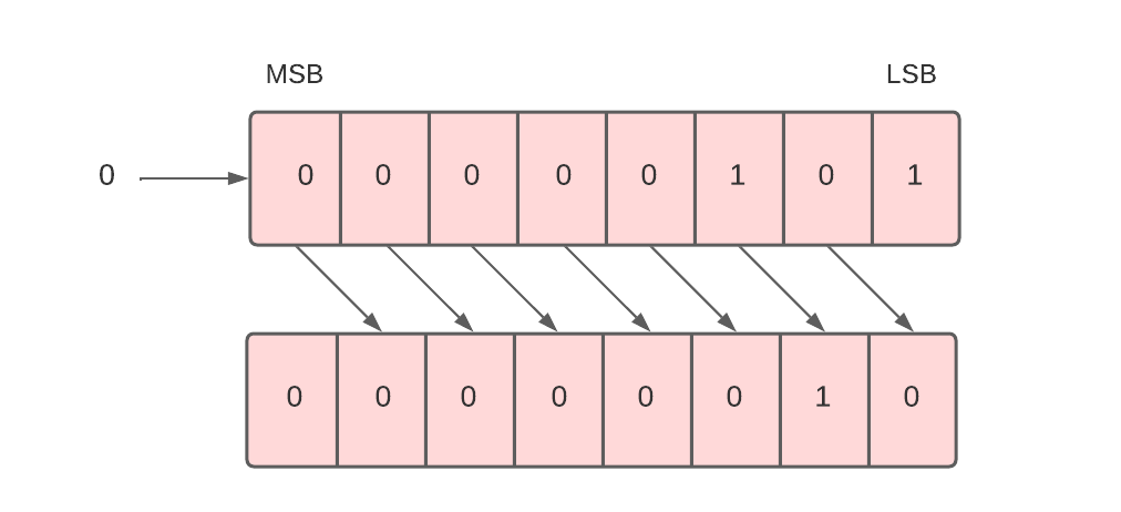
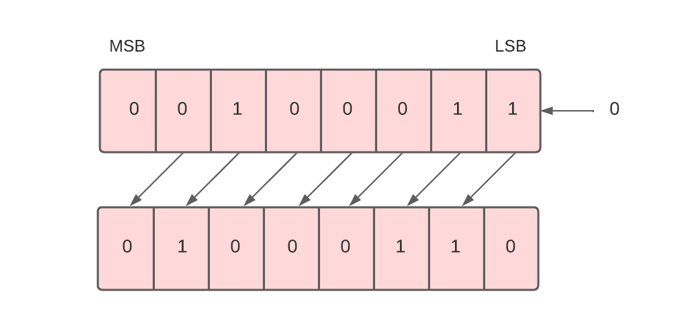
Logical Shift Left
Each bit in the register is shifted to the left one by one in this shift micro-operation. The most significant bit (MSB) is moved outside the register, and the place of the least significant bit (LSB) is filled with 0.
For example, in the below data, there are 8 bits 00001010. When we perform a logical shift left on these bits, all these bits will be shifted towards the left. The MSB or the leftmost bit i.e. 0 will be moved outside, and at the rightmost place or LSB, 0 will be inserted as shown below.
To implement the logical shift left micro-operation, we use the shl symbol.
For example, R1 -> shl R1.
This command means the 8 bits present in the R1 register will be logically shifted left, and the result will be stored in register R1.
Moreover, the logical shift left microoperation denotes the multiplication of 2. The example we’ve taken above when converted into decimal forms the number 10. And the result after the logical shift operation when converted to decimal forms the number 20.
Next, we will see the logical shift right micro-operation.
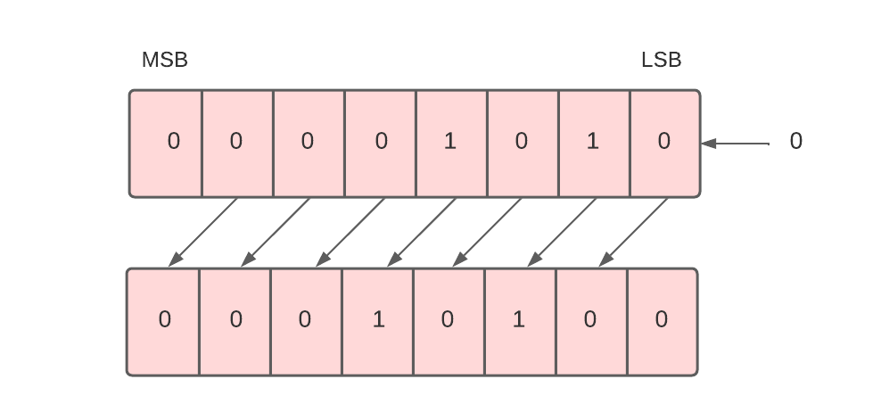
Logical Shift Right
Each bit in the register is shifted to the right one by one in this shift micro-operation. The least significant bit (LSB) is moved outside the register, and the place of the most significant bit (MSB) is filled with 0.
For example, in the below data, there are 8 bits 00000101. When we perform a logical shift right on these bits, all these bits will be shifted towards the right. The LSB or the rightmost bit i.e. 1 will be moved outside, and at the leftmost place or MSB, 0 will be inserted as shown below.
To implement the logical shift right micro-operation, we use the shr symbol.
For example, R1 -> shr R1.
This command means the 8 bits present in the R1 register will be logically shifted right, and the result will be stored in register R1.
Logical right shift micro-operation generally denotes division by 2. The inputted bits when converted into decimal form the number 5. And the outcome when converted into decimal forms the number 2.
Next, we will study arithmetic shift micro-operation.
Arithmetic Shift
The arithmetic shift micro-operation moves the signed binary number either to the left or to the right position. There are two ways to implement the arithmetic shift.
- Arithmetic Shift Left
- Arithmetic Shift Right
Let’s discuss both of them one by one.
Arithmetic Shift Left
The arithmetic shift left micro-operation is the same as the logical shift left micro-operation. Each bit in the register is shifted to the left one by one in this shift micro-operation. The most significant bit (MSB) is moved outside the register, and the place of the least significant bit (LSB) is filled with 0.
For example, in the below data, there are 8 bits 00100011. When we perform the arithmetic shift left on these bits, all these bits will be shifted towards the left. The MSB or the leftmost bit i.e. 0 will be moved outside, and at the rightmost place or LSB, 0 will be inserted as shown below.
The given binary number (00100011) represents 35 in the decimal system. And the binary number after logical shift left (01000110) represents 70 in a decimal system. Since 35 * 2 = 70. Therefore, we can say that the arithmetic shift left multiplies the number by 2.
To implement the arithmetic shift left micro-operation, we use the ashl symbol.
For example, R1 -> ashl R1.
This command means the 8 bits present in the R1 register will be arithmetic shifted left, and the result will be stored in register R1.
Arithmetic Shift Right
Each bit in the register is shifted to the right one by one in this shift micro-operation. The least significant bit (LSB) is moved outside the register, and the place of the most significant bit (MSB) is filled with the previous value of MSB.
For example, in the below data, there are 8 bits 10100011. When we perform an arithmetic shift right on these bits, all these bits will be shifted towards the right. The LSB or the rightmost bit i.e. 1 will be moved outside, and at the leftmost place or MSB, the previous MSB value, i.e. 1, will be inserted as shown below.
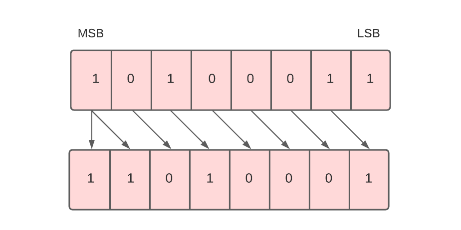
Arithmetic right shift divides the number by 2.
To implement the arithmetic shift right micro-operation, we use the ashr symbol.
For example, R1 -> ashr R1.
This command means the 8 bits present in the R1 register will be arithmetic shifted right, and the result will be stored in register R1.
Next, we will study circular shift micro-operation.
Circular Shift
The circular shift, also known as the rotate shift, moves the bits in the register’s sequence around both ends, thus ensuring no loss of information. There are two ways to implement the circular shift.
- Circular Shift Left
- Circular Shift Right
Let’s discuss both of them one by one.
Circular Shift Left
Each bit in the register is shifted to the left one by one in this shift micro-operation. After shifting, the least significant bit (LSB) place becomes empty, so it is filled with the value at the most significant bit (MSB).
For example, in the below data, there are 8 bits 00010100. When we perform a circular shift left on these bits, all these bits will be shifted towards the left. The MSB or the leftmost bit i.e. 0 will be placed at the rightmost place or LSB as shown below.
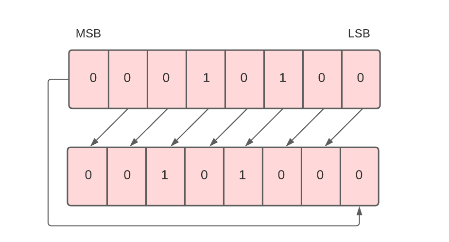
To implement the circular shift left micro-operation, we use the cil symbol.
For example, R1 -> cil R1.
This command means the 8 bits present in the R1 register will be circular shifted left, and the result will be stored in register R1.
Next, we will discuss circular shift right micro-operation.
Circular Shift Right
Each bit in the register is shifted to the right one by one in this shift micro-operation. After shifting, the most significant bit (MSB) place becomes empty, so it is filled with the value at the least significant bit (LSB).
For example, in the below data, there are 8 bits 00010100. When we perform a circular shift right on these bits, all these bits will be shifted towards the right. The LSB or the leftmost bit, i.e. 0, will be placed at the rightmost place or MSB.
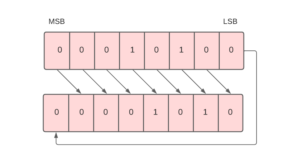
To implement the circular shift right micro-operation, we use the cir symbol.
For example, R1 -> cir R1.
This command means the 8 bits present in the R1 register will be circular shifted right, and the result will be stored in register R1.
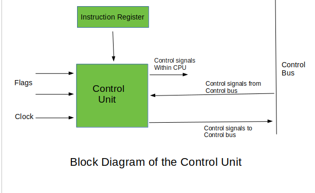
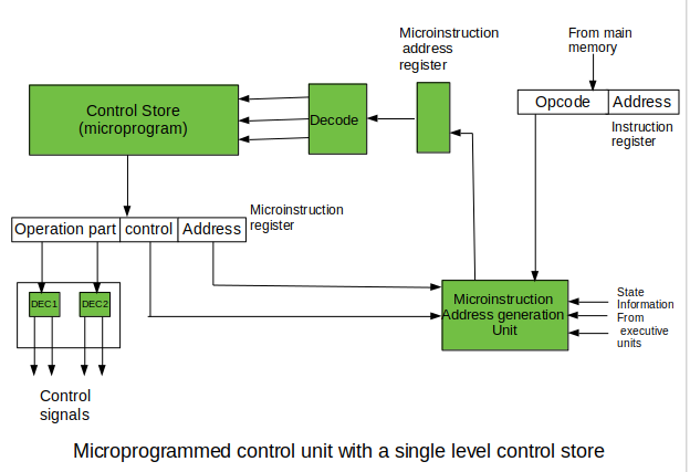 The last mentioned field decides the addressing mode (addressing operation) to be applied to the address embedded in the ongoing microinstruction. In microinstructions along with conditional addressing mode, this address is refined by using the processor condition flags that represent the status of computations in the current program. The last microinstruction in the instruction of the given microprogram is the microinstruction that fetches the next instruction from the main memory to the instruction register.
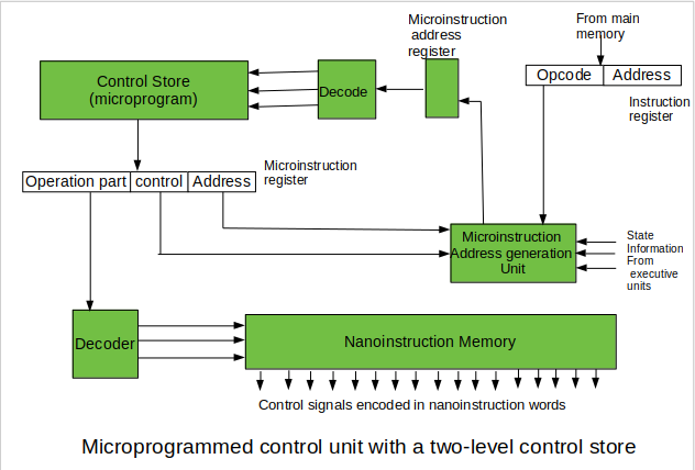 In this way, unnecessary storing of the same operation parts of microinstructions is avoided. In this case, microinstruction word can be much shorter than with the single level control store. It gives a much smaller size in bits of the microinstruction memory and, as a result, a much smaller size of the entire control memory. The microinstruction memory contains the control for selection of consecutive microinstructions, while those control signals are generated at the basis of nano-instructions. In nano-instructions, control signals are frequently encoded using 1 bit/ 1 signal method that eliminates decoding.